Heating furnace system and combustion and heat recovery method of heating furnace system

A heating furnace and waste heat recovery technology, which is applied in the fields of heating furnace system, combustion and heat recovery, can solve the problems of increasing the volume and investment of the heating furnace system, the heat cannot be recovered deeply, and the exhaust gas temperature cannot be too low, so as to achieve favorable Long-term stable operation, reduced floor area and equipment investment costs, reduced volume and investment effects

Pending Publication Date: 2022-07-08
CHINA PETROLEUM & CHEM CORP +1
View PDF7 Cites 0 Cited by
  • Summary
  • Abstract
  • Description
  • Claims
  • Application Information

AI Technical Summary

Problems solved by technology

[0003] In order to ensure the air supply requirements for combustion and to overcome the flue gas flow resistance in the entire heating furnace system, the general heating furnace system is equipped with a blower at the front and a chimney and induced draft fan at the rear, which increases the volume and size of the heating furnace system to a certain extent. invest
In addition, in the flue gas waste heat recovery unit, in order to avoid flue gas dew point corrosion, the exhaust gas temperature should not be too low, so that the heat in the flue gas cannot be recovered deeply, which becomes a bottleneck for further improvement of the thermal efficiency of the heating furnace

Method used


Image

  • Heating furnace system and combustion and heat recovery method of heating furnace system
  • Heating furnace system and combustion and heat recovery method of heating furnace system
  • Heating furnace system and combustion and heat recovery method of heating furnace system

Examples


Embodiment 1

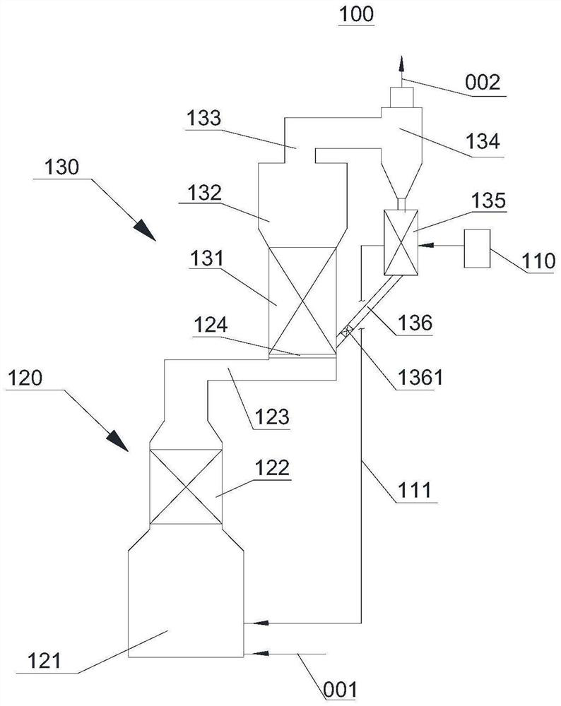
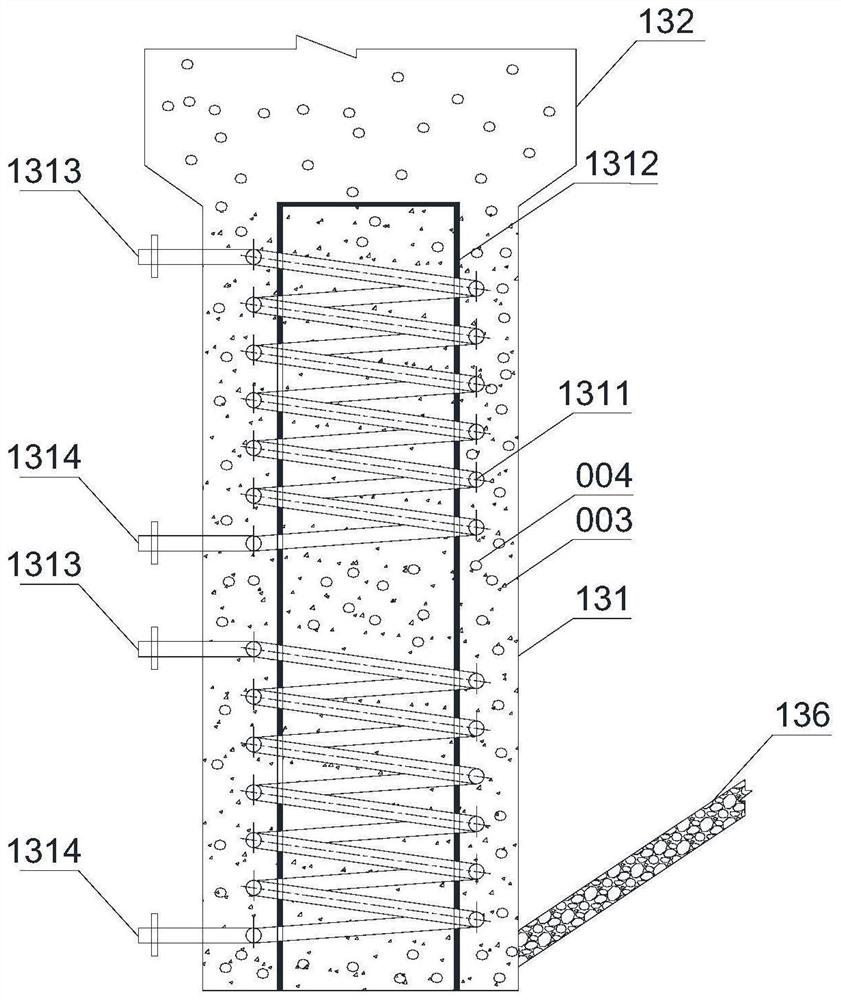
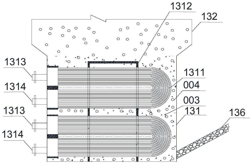
[0062] This embodiment provides a combustion and heat recovery method for a heating furnace system, which adopts figure 1 The device in the device conducts combustion and heat recovery, and the schematic structural diagram of the fluidized bed heat exchange section 131 is as follows figure 2 As shown, the schematic diagram of the structure of the moving bed gas-assisting preheating section 135 is as follows Figure 4 and Figure 5 As shown, the fuel is natural gas for a furnace with a heat load of 12 MW.

[0063] The specific operation steps are as follows:

[0064] The air compressor in the pressure inlet unit 110 will be 10800m 3 The normal temperature and normal pressure air per hour is inhaled, compressed and pressurized to about 180kPa, and after the temperature of the moving bed combustion-assistant preheating section 135 rises, it enters the combustion-assistant gas transmission line 111, and is transported from the fuel transmission line 001 1200m 3 After being mi...


PUM


Abstract

The invention discloses a heating furnace system and a combustion and heat recovery method of the heating furnace system, and relates to the technical field of heating furnaces. Pressurized combustion-supporting gas is provided through the pressure air inlet unit, the pressurized combustion-supporting gas and fuel are mixed and then combusted under pressure in a hearth of a radiation section of the heating furnace, high-temperature flue gas flows at a high speed to form turbulent flow, and convective heat exchange between the high-temperature flue gas and a furnace tube is enhanced. And under the interaction of rapid and sufficient combustion of fuel and turbulent flow of high-temperature flue gas flow, the combustion and heat exchange process in the hearth is more efficient. According to the waste heat recovery unit, a double-fluidizing medium is adopted for efficient heat exchange in a fluidized bed heat exchange section, small hollow metal balls and pressurized combustion-supporting gas are utilized for contact heat exchange in a moving bed combustion-supporting gas preheating section, the purposes of deeply recovering smoke heat and avoiding dew point corrosion are achieved, the heat efficiency of the heating furnace is remarkably improved, and the size and investment of the heat exchange unit are reduced.

Description

technical field [0001] The present invention relates to the technical field of heating furnaces, in particular, to a heating furnace system and a combustion and heat recovery method of the heating furnace system. Background technique [0002] The combustion-supporting air of the heating furnace in the petrochemical enterprise usually adopts the way of natural air intake or forced air intake by blower, and the fuel is burned in the state of slight negative pressure in the furnace. In the radiant chamber of the furnace, the heat exchange between the high temperature flue gas produced by combustion and the furnace tube is mainly radiation heat exchange, and the proportion of convection heat exchange is small. The high-temperature flue gas after combustion leaves the radiation chamber of the heating furnace, and after the heat is recovered after passing through the convection section, it enters the waste heat recovery unit to further recover the sensible heat of the flue gas and...

Claims


Application Information

Patent Timeline
Patent Type & Authority Applications(China)
IPC IPC(8): F27D17/00F23J15/08F23J15/02F28D13/00F28D19/02F23L15/00
CPCF27D17/004F27D17/00F23J15/08F23J15/027F28D13/00F28D19/02F23L15/00F27D2017/009Y02P10/25
Inventor 周天宇张婧帆李玖重孙志钦牛风宾郜建松王恒博苏耀伦李晓睿
Owner CHINA PETROLEUM & CHEM CORP
Why Eureka
Try Eureka