Variable printing machine

A printing press, variable technology, applied in printing presses, rotary printing presses, screen printing presses, etc., can solve the problems of inability to increase tension, easy to bump, unable to prevent snake spots, etc., to eliminate printing stains, eliminate bumps, etc. effect of injury

Inactive Publication Date: 2006-09-13
MIYAKOSHI PRINTING MACHINERY
View PDF1 Cites 3 Cited by
  • Summary
  • Abstract
  • Description
  • Claims
  • Application Information

AI Technical Summary

Problems solved by technology

[0008] But, when using plastic film as the material to be printed, since the material to be printed is easy to be scratched, and is easily attached to the cylinder by static electricity, it is inevitable to produce scratches and scratches caused by the friction between the pressure cylinder and the rubber cylinder. print stain
[0009] In addition, in the case of using thin printed materials such as paper and film, when the feed path between the two feed rollers reaches 7m or more, when the tension of the printed material is increased to suppress the slack and shake in the middle, because New problems caused by stretching and cutting occur, so tension cannot be increased and snake spots cannot be prevented

Method used


Image

  • Variable printing machine
  • Variable printing machine
  • Variable printing machine

Examples


Embodiment Construction

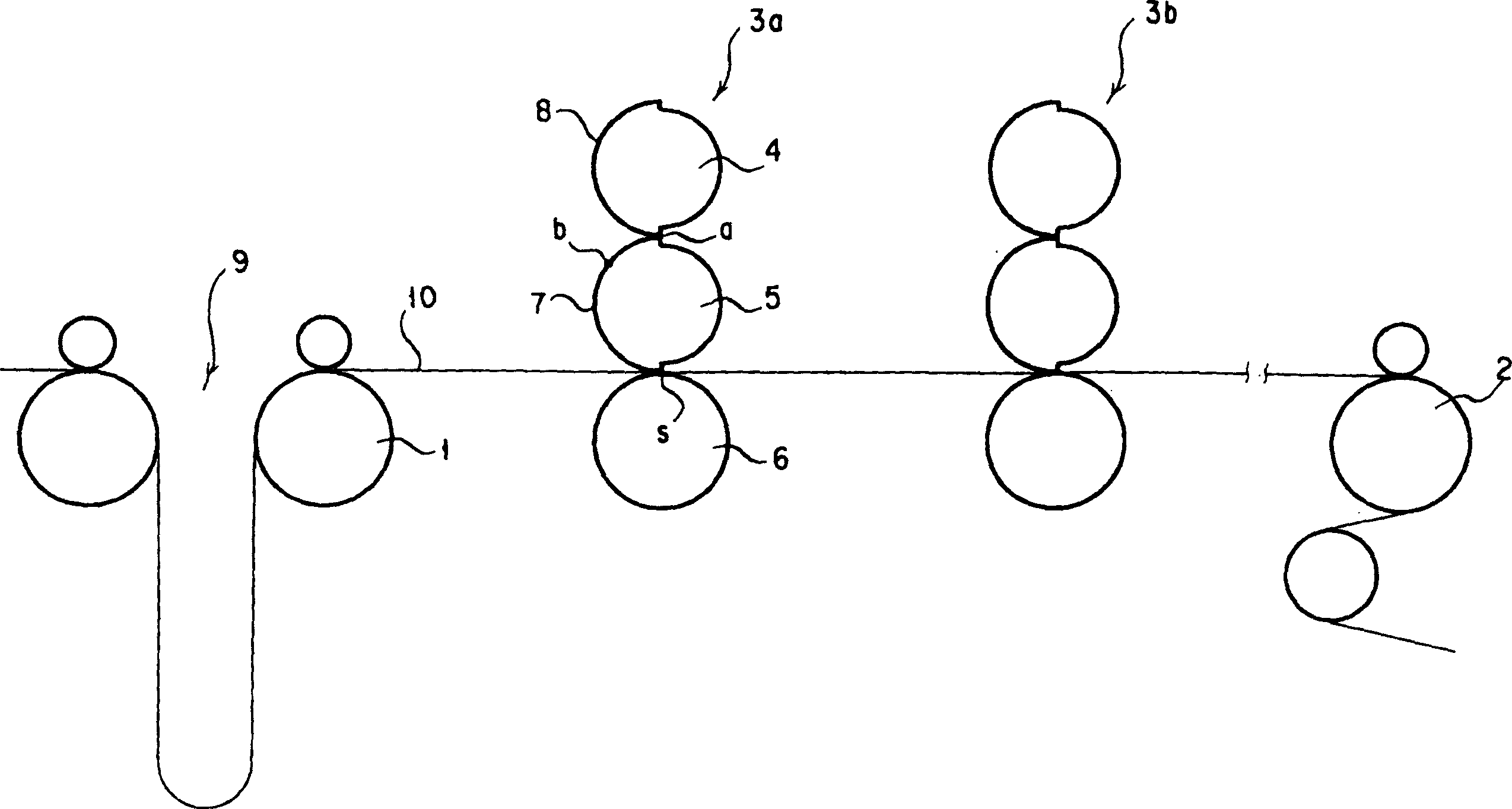
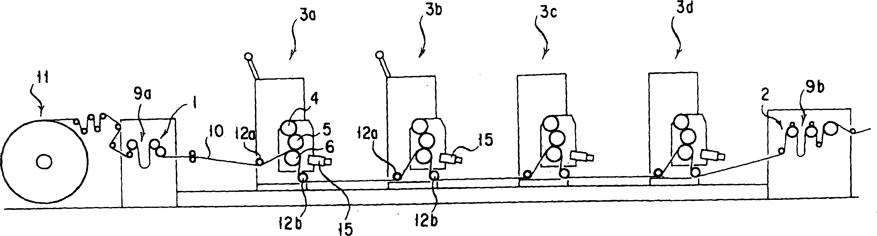
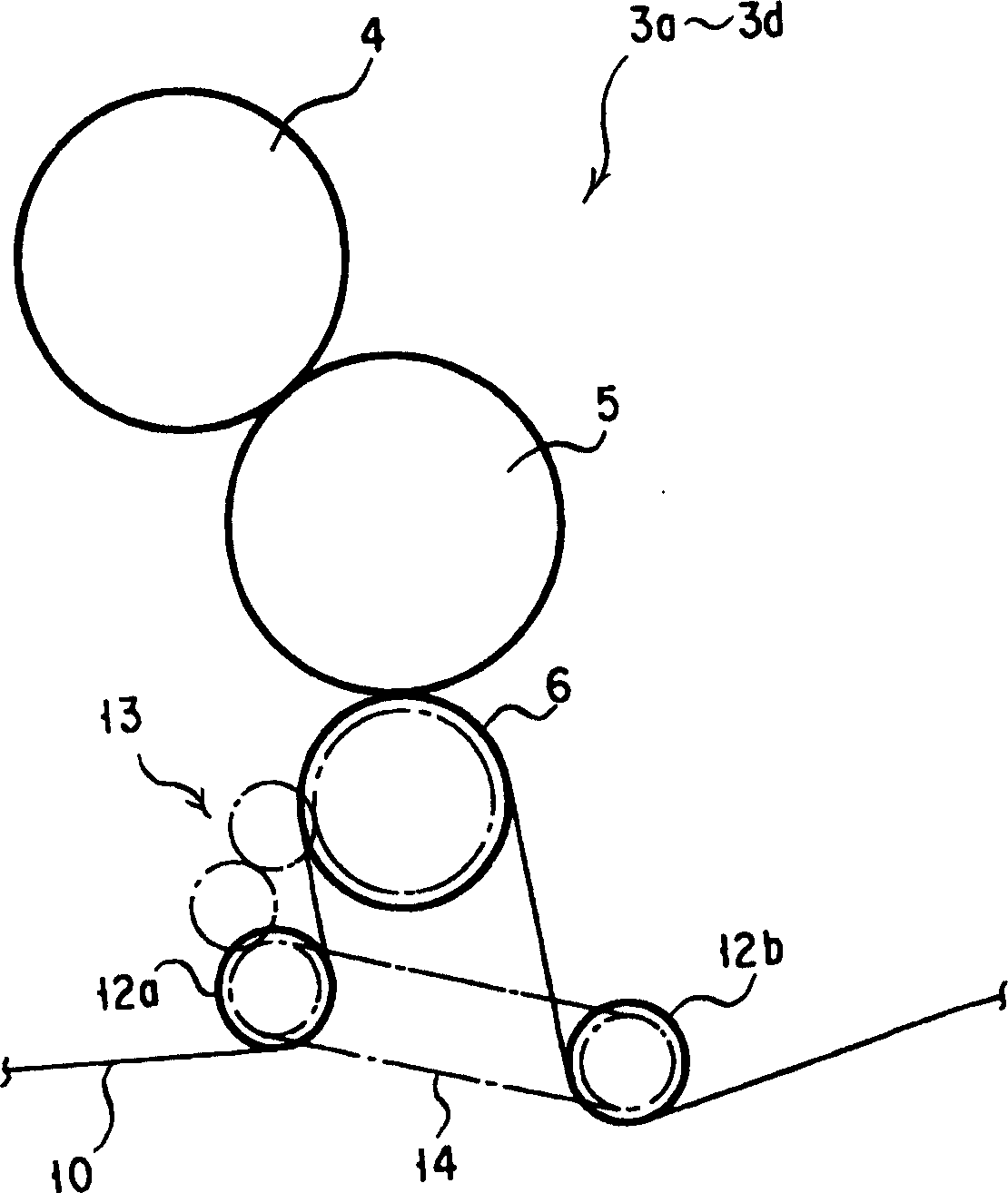
[0026] An example of the variable printing machine of the present invention consists of figure 2 with image 3 illustrate. In the figure with figure 1 The same components of the shown prior art are described with the same reference numerals.

[0027] Multiple sets (four sets) are arranged in the travel path between the feed rollers 1 and 2 on the upstream side and the downstream side of the continuous paper 10 in the traveling direction. The printing cylinder 4, the blanket cylinder 5, and the platen cylinder 6 constitute a variable printing machine. Printing units 3a, 3b, 3c, 3d. The printing cylinder 4 and the blanket cylinder 5 of each of the printing units 3a to 3d rotate at the same peripheral speed in the running direction of the continuous paper 10 . In addition, in figure 2 Not shown in the figure, a printing plate and a blanket are installed on the large-diameter outer peripheral surfaces of the printing cylinder 4 and the blanket cylinder 5, respectively. In ...


PUM


Abstract

One changeable printing machine capable of printing on plastic film and other thin material fluently without loosening and shaking is disclosed. The changeable printing machine has pressing drums of the printing unit set between one pair of feeding rollers rotating symmetrically with the feeding rollers and each of the pressing drums is provided with guide roller in at least one of the upstream side and the downstream side for the printed material to pass through between the printing drum and the pressing drum.

Description

technical field [0001] The present invention relates to variable printing presses. Background technique [0002] Such as figure 1 As shown, the offset type variable printing machine is provided with a plurality of printing units 3a, 3b for variable printing between a pair of feed rollers 1, 2 which can be synchronously rotated forward and reverse in the horizontal direction. This each printing unit 3a, 3b is made up of printing cylinder 4, blanket cylinder 5 and pressure cylinder 6, and the outer peripheral surface of blanket cylinder 5 is provided with the large-diameter part that becomes the printing surface of half circumference s-a for example, at this large-diameter part Rubber 7 is installed on the peripheral surface. [0003] In addition, a printing plate 8 having a circumference shorter than the circumference s-a of the abutting portion is attached to a portion of the printing cylinder 4 that abuts against the large-diameter portion of the blanket cylinder 5. As sh...

Claims


Application Information

Patent Timeline
Patent Type & Authority Applications(China)
IPC IPC(8): B41F13/02B41F22/00B65H23/00B65H20/02
Inventor 仲正裕藤原铃司进藤达也
Owner MIYAKOSHI PRINTING MACHINERY
Why Eureka
Try Eureka