Vacuum cleaner

A vacuum cleaner, electric technology, applied in the direction of vacuum cleaners, cleaning equipment, household appliances, etc., can solve the problems of high noise, noise impact, low efficiency, etc., and achieve the effect of reducing noise, high suction performance, and reducing exhaust sound

Inactive Publication Date: 2006-09-20
PANASONIC CORP
View PDF2 Cites 7 Cited by
  • Summary
  • Abstract
  • Description
  • Claims
  • Application Information

AI Technical Summary

Problems solved by technology

[0009] However, in the above structure, in order to improve the suction efficiency of the electric vacuum cleaner, although the first and second discharge ports are respectively provided on the fan side and the motor part side of the electric blower, there is only one on the box covering the electric blower. There is a discharge port on the part, and the efficiency is not high
In addition, in order not to form resistance to the flow of exhaust gas, if the outlet is enlarged, although the efficiency of the suction can be imp

Method used


Image

  • Vacuum cleaner
  • Vacuum cleaner
  • Vacuum cleaner

Examples


Embodiment 1

[0044] Refer below Figure 1 to Figure 5 The first embodiment of the present invention will be described.

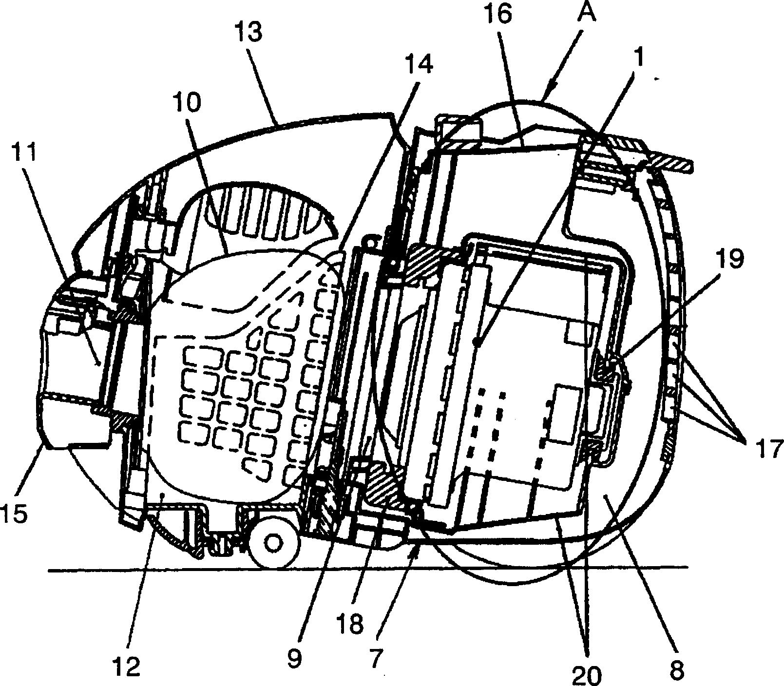
[0045] figure 1 , figure 2 Among them, the electric blower 1 that generates suction wind includes a fan part 4 and a motor part 6. The fan part 4 is composed of an impeller (not shown) that generates wind by rotation, an air inlet 2 for sucking air, and a housing 4a that covers the impeller. and the first exhaust port 3 that discharges the wind generated by the impeller to the outside. The motor part 6 houses the rotational power of the impeller, that is, the motor, and is arranged on the bracket 6a that covers the motor and drives the impeller to the outside. The second exhaust port 5 through which the generated air is discharged to the outside is constituted. 7 is an electric vacuum cleaner body, the electric blower chamber 8 in which the electric blower 1 is arranged, the suction port 9 communicating with the suction port 2 on the upstream side of the suction por...

Embodiment 2

[0063] Refer below Figure 6 ~ Figure 12 A second embodiment of the present invention will be described.

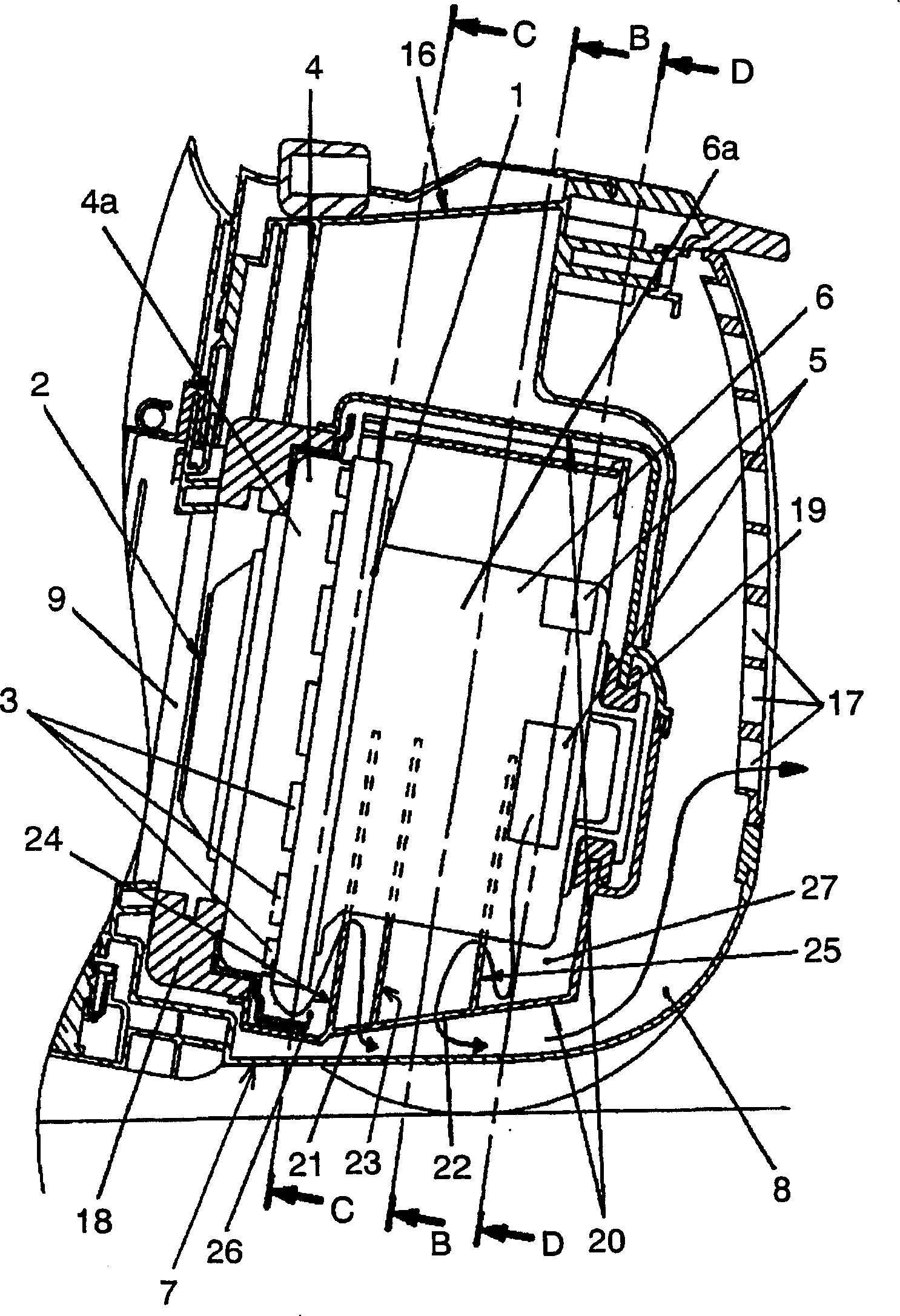
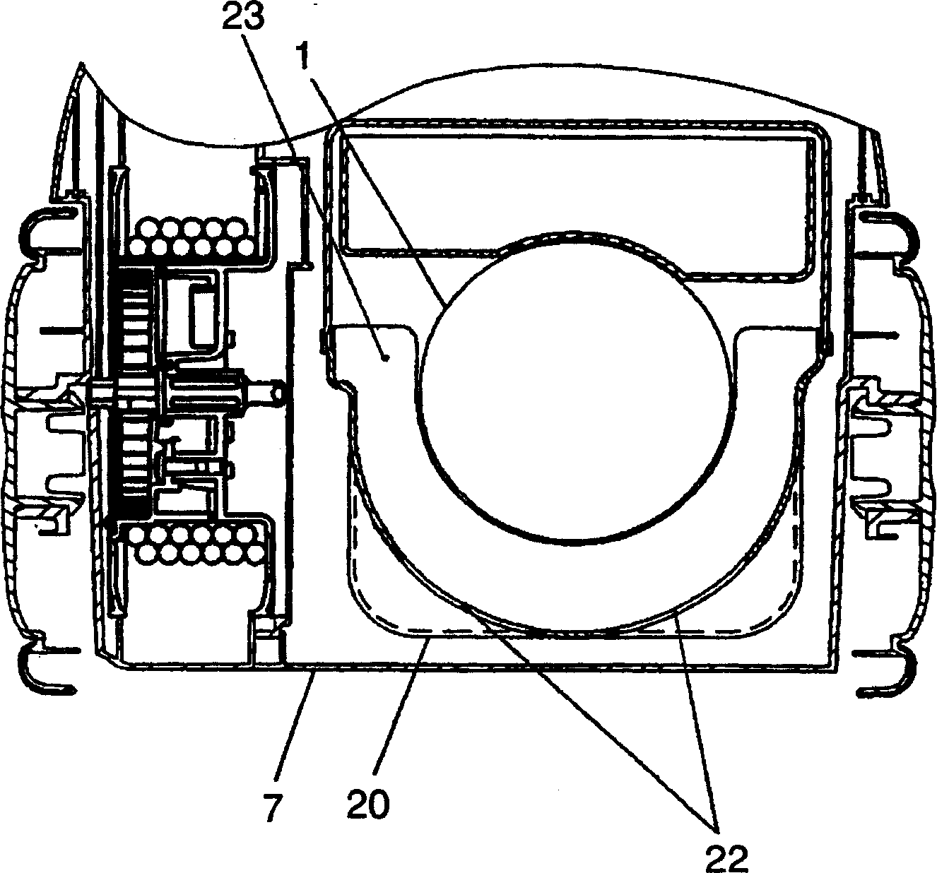
[0064] Image 6 , Figure 7 Among them, the electric blower 111 that generates suction wind is composed of an air inlet 112, a fan unit 114 having first exhaust ports 113 arranged at regular intervals, and a motor unit 116 that generates rotational power and has second exhaust ports 115. constitute. 117 is an electric vacuum cleaner body, the electric blower chamber 118 in which the electric blower 111 is configured, the suction port 119 communicating with the suction port 112 on the upstream side of the suction port 112 of the electric blower 111, and the paper bag 120 for collecting dust are arranged. A suction device (not shown) for sucking dust on the upstream side of the paper bag 120 and a dust collection chamber 122 having a suction port 121 communicating with the paper bag 120 are constituted. Above the dust collecting chamber 122 is formed a dust collecting c...

Embodiment 3

[0081] refer to Figure 13 , Figure 14 A third embodiment of the present invention will be described. In addition, the same code|symbol is attached|subjected to the same part as the above-mentioned embodiment, and the description is abbreviate|omitted.

[0082] On the outer rear side of the outlet 132 provided in the lower muffler box 130b, there is provided a detour wall 144 formed in a substantially arc shape with a convex front end on the side of the outlet 132 of the lower muffler box 130b. At the rear of the detour wall 144 , a sound absorbing material 145 is fixed along the wall surface of the detour wall 144 .

[0083] Next, the operation and function of the electric vacuum cleaner constructed as above will be described.

[0084] Since the exhaust gas flowing out of the muffler box 130 flows smoothly along the substantially arc-shaped detour wall 144, there is no loss of exhaust air and high suction performance can be maintained. Moreover, the exhaust air is bent by...


PUM


Abstract

The invention relates to an electric dust cleaner with high adsorb property and sound adsorb property, which comprises: an electric fan for generating adsorb wind with an exhaust outlet; an electric fan room that at least partly covering said electric fan; and a main body exhaust outlet for discharging the discharge wind from the electric fan room to the air; on the box, an outlet is arranged to discharge the discharge wind of electric fan outside the box, and a bypass wall is arranged to bypass the discharge wind of said outlet. The inventive electric dust cleaner can realize high adsorb efficiency, reduce noise and adsorb noise.

Description

[0001] This application is a divisional application of a Chinese patent application entitled "Electric Vacuum Cleaner" with an application date of August 23, 2004 and an application number of 200410064261.6. technical field [0002] The present invention relates to an electric vacuum cleaner capable of achieving both high suction performance and quietness. Background technique [0003] In a conventional electric vacuum cleaner, the electric blower is composed of a fan portion having an air suction portion for sucking in suction air, and a motor portion for generating rotational power. In order to improve the suction efficiency of the electric vacuum cleaner, a first exhaust port is provided around the fan cover, and a second exhaust port is provided at the motor part to reduce the amount of suction wind passing through the motor part with a large pressure loss. [0004] There is a structure in which around the electric blower, on the downstream side of the first exhaust port...

Claims


Application Information

Patent Timeline
IPC IPC(8): A47L5/00A47L9/00
Inventor 奥岛雅史仲本博司伊藤幸一北村秀典
Owner PANASONIC CORP
Why Eureka
Try Eureka