

Combined garbage transit station
A transfer station, combined technology, applied in the direction of garbage conveying, garbage collection, transportation and packaging, can solve the problems of loose garbage, high moisture content and high cost of garbage station construction
Active Publication Date: 2010-11-10
广西玉柴专用汽车有限公司
View PDF2 Cites 0 Cited by
- Summary
- Abstract
- Description
- Claims
- Application Information
AI Technical Summary
Problems solved by technology
With the gradual increase of the world's population, people produce more and more garbage in their daily lives, and the environmental pollution of the earth is becoming more and more serious. Therefore, the society must invest a lot of money in transporting and disposing of garbage. However, due to urban The directly collected garbage is relatively loose. In order to improve the efficiency of garbage transportation, people must compress the garbage. In the existing garbage trucks and garbage transfer stations, we found that there are some new problems. First, because most of the garbage transfer The compression of garbage at the station does not use horizontal or vertical compression, so the garbage compressed into the compartment is relatively loose and has a lot of water; A set of mechanical lifting mechanism is installed in the station, so that the cost of the garbage station is high, as the Chinese patent: urban waste buried type micro-processing device (application number: 02232914.5) discloses a kind of urban waste buried type micro-processing device, in the ground Under the plane, a rectangular hollow body is set, a garbage container is installed in the front part of the hollow body, and a compressed garbage working chamber is installed in the rear part of the working room. The compressor is connected with the garbage propulsion device to push the garbage into the garbage container. The top of the compressor is equipped with a material inlet and a movable cover, and the outside is equipped with a docking locking device to fix the compressor and the sealing plate of the garbage container. , lifting device, and can open the sealing plate of the sealed container. The bottom of the container is equipped with a sewage discharge port, the bottom is equipped with a locator, and the top is equipped with a hoisting ring.
Method used
View moreImage
Smart ImageViewing Examples

Examples
Embodiment Construction
Login to View More PUM
 Abstract
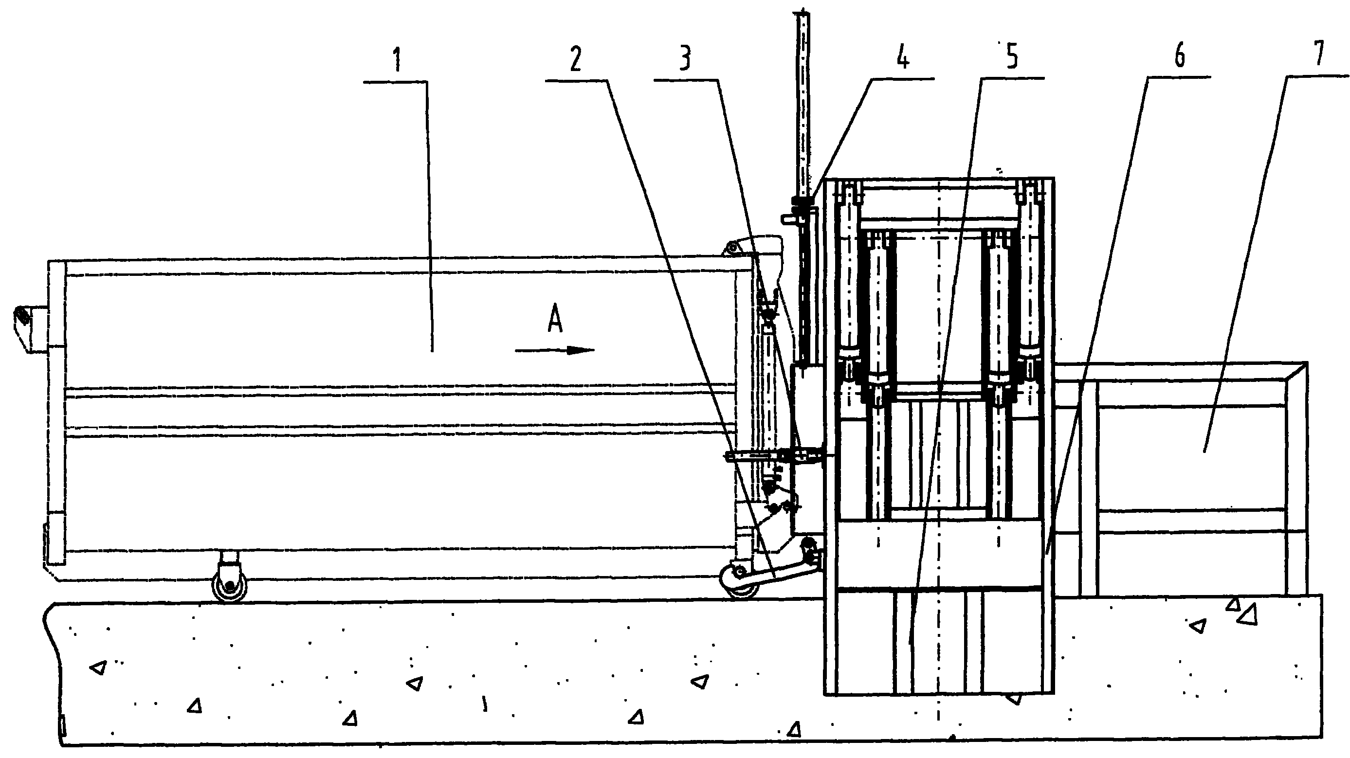
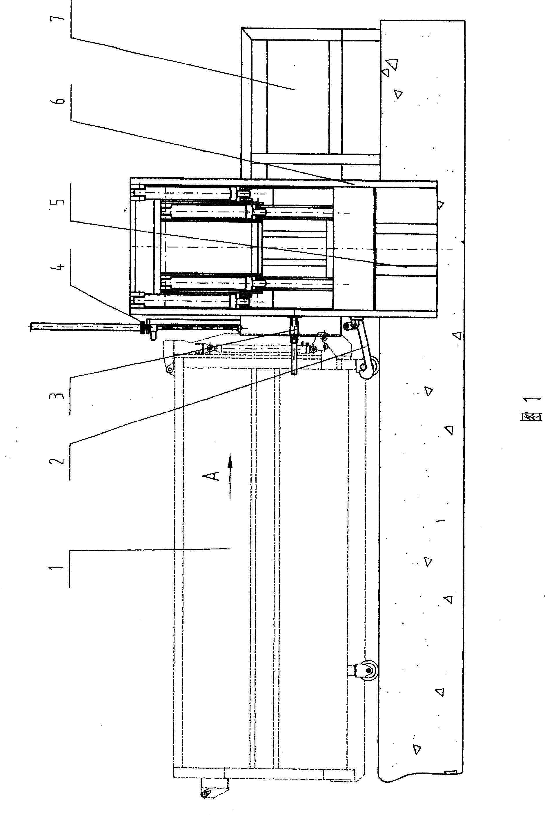
A combined garbage transport station is composed of garbage carriage, locking hook module, main gate, hydraulic system, combined carriage body butt-connected to said garbage carriage via said locking hook module, and carriage body moving mechanism. It can automatically break off garbage, lift it up and horizontally compress it.
Description
Combined refuse transfer station technical field The invention relates to a kind of urban garbage mechanical equipment, in particular to a horizontal piston type compressed garbage transfer station. Background technique With the gradual increase of the world's population, people produce more and more garbage in their daily lives, and the environmental pollution of the earth is becoming more and more serious. Therefore, the society must invest a lot of money in transporting and disposing of garbage. However, due to urban The directly collected garbage is relatively loose. In order to improve the efficiency of garbage transportation, people must compress the garbage. In the existing garbage trucks and garbage transfer stations, we found that there are some new problems. First, because most of the garbage transfer The compression of garbage at the station does not use horizontal or vertical compression, so the garbage compressed into the compartment is relatively loose and ha...
Claims
Login to View More Application Information
Patent Timeline
 Patent Type & AuthorityPatents(China)
IPC IPC(8): B65F9/00
Inventor刘英华杨照刚邓树林陆愈天章霞东颜伟才杨德权秦建宁
Owner广西玉柴专用汽车有限公司