High efficiency and power fiber optic rotary joint

a rotary joint, high efficiency technology, applied in the direction of optics, instruments, optical light guides, etc., can solve the problems of high power handling capability of limited power handling capabilities of typical power limitations associated with conventional fiber optic rotary joints, etc., to achieve low power handling capabilities and high coupling losses

Active Publication Date: 2018-06-26
BAE SYST INFORMATION & ELECTRONICS SYST INTERGRATION INC
View PDF9 Cites 7 Cited by
  • Summary
  • Abstract
  • Description
  • Claims
  • Application Information

AI Technical Summary

Benefits of technology

[0004]Issues continue to exist with transmitting optical signals via a fiber optic rotary joint. Exemplary issues are low power handling capabilities and high coupling losses. The present disclosure addresses these and other issues.

Problems solved by technology

Further, typical fiber optic rotary joints may have high insertion loss (e.g. 3 dB (50%) to 10 dB (90%)), which may limit the total power handling capabilities of typical fiber optic rotary joints.
The power limitations associated with conventional fiber optic rotary joints are driven by the design of the fiber optic cable-fiber optic cable interface.
Such lenses typically cannot operate at high optical powers.
Further, conventional fiber optic rotary joints are generally too lossy which may eventually lead to fiber optic cable tip failure and utilize generally small beams that may lead to reduced damage threshold limitations at high power.
Issues continue to exist with transmitting optical signals via a fiber optic rotary joint.
Exemplary issues are low power handling capabilities and high coupling losses.

Method used


Image

  • High efficiency and power fiber optic rotary joint
  • High efficiency and power fiber optic rotary joint
  • High efficiency and power fiber optic rotary joint

Examples


Embodiment Construction

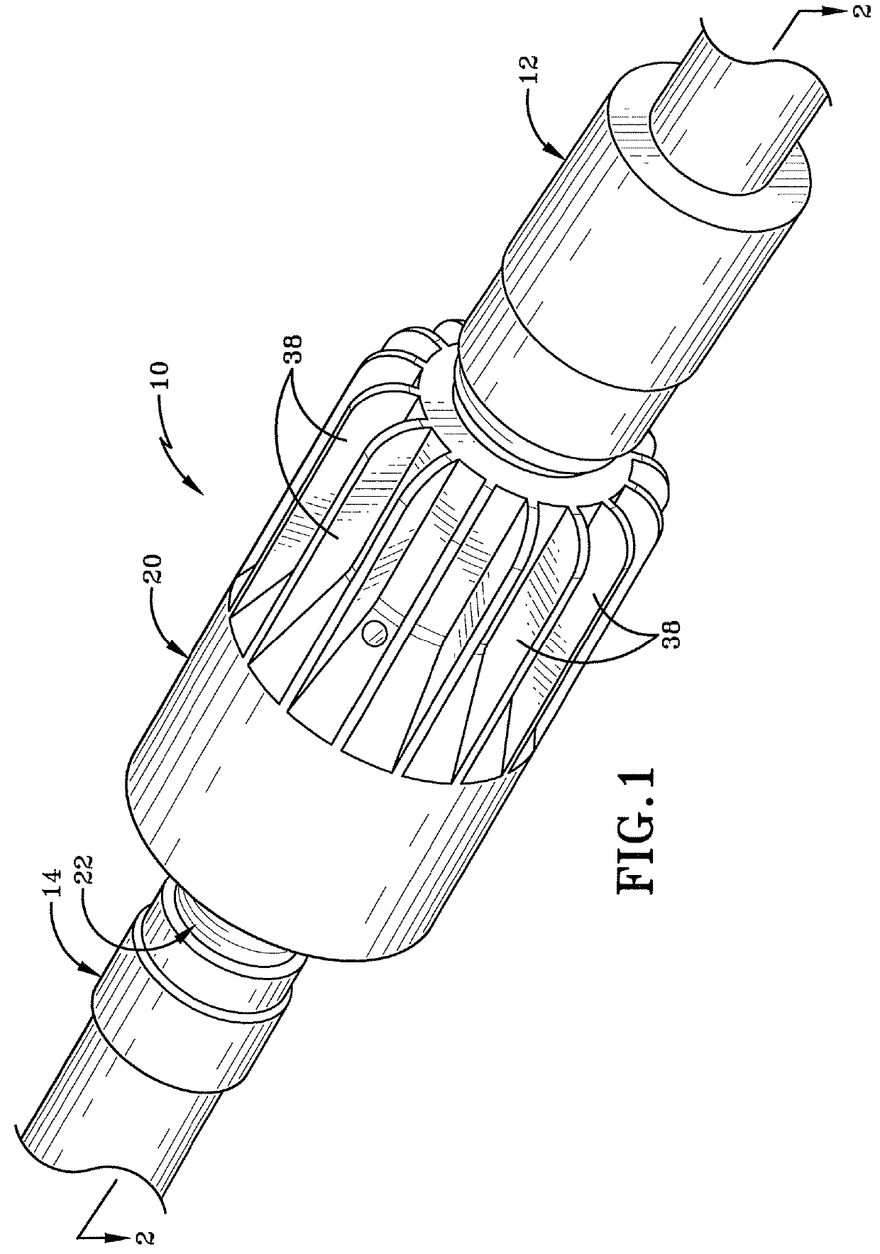
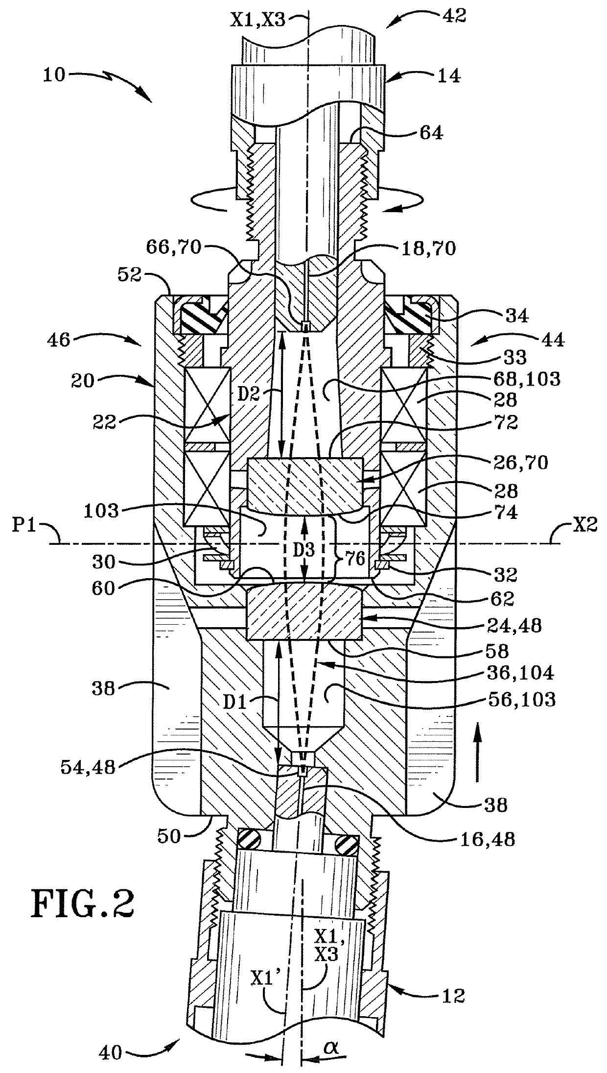
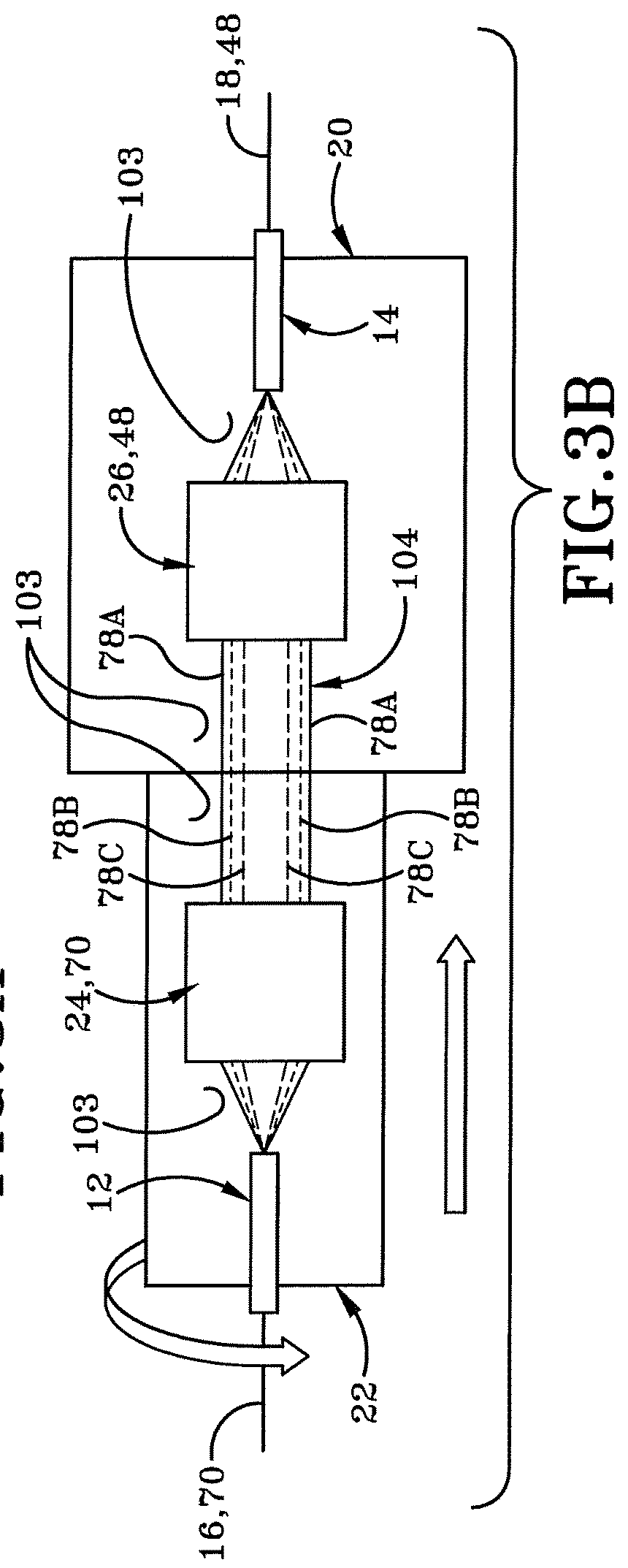
[0027]A fiber optic rotary joint (FORJ) is generally depicted in FIG. 1 and FIG. 2 and is shown generally at 10. The FORJ 10 includes an input fiber optic connector 12, an output fiber optic connector 14, a first fiber optic cable 16, a second fiber optic cable 18, a stator 20, a rotor 22, a first beam conditioning mechanism 24, a second beam conditioning mechanism 26, at least one bearing 28, at least one wave spring 30, a retaining ring 32, a mounting ring 33, a dynamic environmental seal 34, a light beam 36 and at least one radial fin 38.

[0028]The FORJ 10 includes a first end 40 and a second end 42 defining a longitudinal direction therebetween. The first end 40 and the second end 42 define a longitudinal axis X1 extending along the center of the FORJ 10 from the second end 42 towards the first end 40. The FORJ 10 further includes a right side 44 and a left side 46 defining a transverse direction therebetween. The right side 44 and the left side 46 define a transverse axis X2 ext...


PUM


Abstract

A fiber optic rotary joint includes a first fiber optic cable operably coupled to one of a stator and a rotor and a second fiber optic cable operably coupled to the other of the stator and the rotor. The stator and the rotor define a free space optical path between the first fiber optic cable and the second fiber optic cable. The rotor is rotatable about an axis of rotation parallel and collinear with an optical axis of at least one end of the fiber optic rotary joint. A first beam conditioning mechanism is configured to condition a light beam emitted from the first fiber optic cable and a second beam conditioning mechanism is configured to focus the conditioned light beam into the second fiber optic cable.

Description

BACKGROUNDTechnical Field[0001]The present disclosure relates generally to the field of transmitting optical signals. More particularly, the present disclosure relates to transmitting optical signals via a fiber optic rotary joint. Specifically, the present disclosure relates to transmitting high power optical signals with high coupling efficiency via a fiber optic rotary joint.Background Information[0002]Generally, fiber optic rotary joints transmit optical signals carried by fiber optic cables through a rotary interface. Fiber optic rotary joints are typically used to transmit very low power (i.e. <<10 watts) high-speed data signals for telecommunication applications where appreciable signal loss (i.e. >25%) is often permissible based on available signal-to-noise ratios (SNR). Further, typical fiber optic rotary joints may have high insertion loss (e.g. 3 dB (50%) to 10 dB (90%)), which may limit the total power handling capabilities of typical fiber optic rotary joints.[...

Claims


Application Information

Patent Timeline
Patent Type & Authority Patents(United States)
IPC IPC(8): G02B6/36G02B6/35
CPCG02B6/3604G02B6/3592G02B6/2706G02B6/29361
Inventor JOHNSON, BENJAMIN R.JEW, JEFFREY L.SHAW, MICHAEL J.STAVER, PHILIP R.
Owner BAE SYST INFORMATION & ELECTRONICS SYST INTERGRATION INC
Why Eureka
Try Eureka