Photoacoustic probe and optical system applied to photoacoustic imaging

A technology of photoacoustic probe and light outlet, which is applied in the field of optical systems, can solve the problems of limited optical energy of fiber bundles, high coupling loss, high coupling loss due to nonlinear effects of optical fibers, etc.

Active Publication Date: 2019-04-09
TSINGHUA UNIV
View PDF5 Cites 6 Cited by
  • Summary
  • Abstract
  • Description
  • Claims
  • Application Information

AI Technical Summary

Problems solved by technology

[0003] In the photoacoustic imaging system of the prior art, the optical fiber is usually used to transmit the laser, but there are the following problems in the optical fiber transmission: first, the optical fiber is prone to nonlinear effects and higher coupling loss (typically 60% ), which limits the optical energy transmitted by the optical fiber bundle; secondly, the optical fiber bundle and its protective sleeve have a certain weight, and are not convenient for doctors to operate and easily oppress the patient's body; one end of the optical fiber bundle connected to the photoacoustic probe has a l...

Method used


Image

  • Photoacoustic probe and optical system applied to photoacoustic imaging
  • Photoacoustic probe and optical system applied to photoacoustic imaging
  • Photoacoustic probe and optical system applied to photoacoustic imaging

Examples


Embodiment Construction

[0084] In order to make the object, technical solution and advantages of the present invention clearer, the present invention will be further described in detail below with reference to the accompanying drawings and examples.

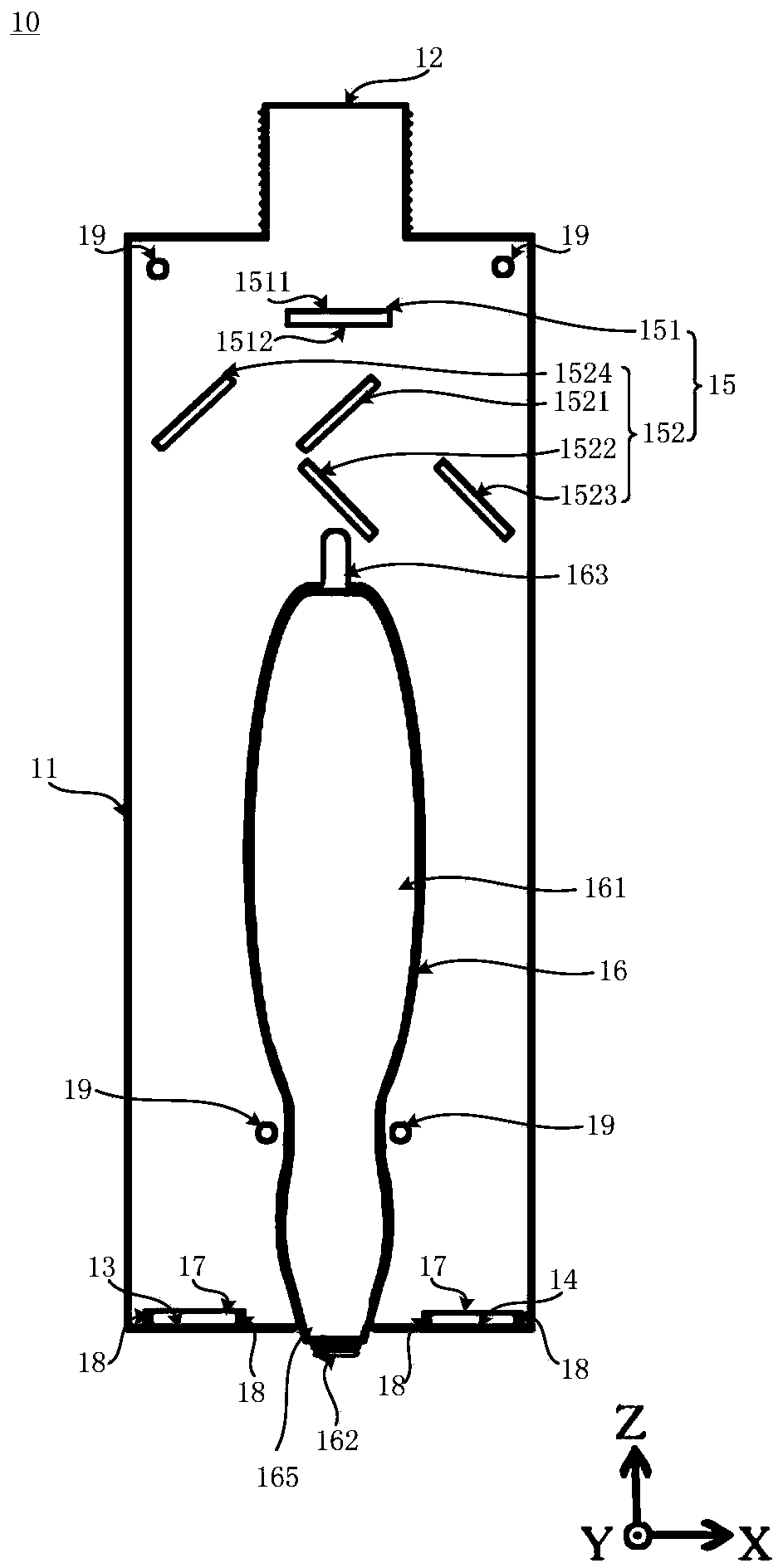
[0085] See figure 1 , figure 1 It is a schematic cross-sectional structure diagram of a photoacoustic probe in an embodiment of the present invention. In one embodiment, the photoacoustic probe 10 includes: a housing 11, a light processing device 15 and an ultrasonic probe 16, wherein the housing 11 has a light inlet 12, a first light outlet 13 and a second light outlet 14; The light processing device 15 is located in the housing 11, and receives the incident light from the light inlet 12, the incident light can be the laser light transmitted by the light guide arm 20, and the light processing device 15 can perform light shaping on the received incident light. Adjust and split the light into a first outgoing light and a second outgoing light parallel ...


PUM


Abstract

The invention discloses a photoacoustic probe and an optical system provided with the photoacoustic probe and applied to photoacoustic imaging. The optical system comprises a laser, a light spot adjusting device, a light guide arm and the photoacoustic probe. The light guide arm ensures that the system has high light energy transmission efficiency and is conveniently operated by doctors. The photoacoustic probe comprises a casing, a light processing device and an ultrasonic probe, wherein the casing is provided with a light inlet, a first light outlet and a second light outlet; the light processing device is positioned in the casing, and is used for receiving incident light and performing light shape adjustment, and finally transmitting light to the first light outlet and the second outletand emitting the light to irradiate a tested sample; the ultrasonic probe is positioned in the casing, and is used for receiving photoacoustc signals from the tested sample and converting the photoacoustc signals into electric signals, so as to output the electric signals. As an engineering effuser is mounted in the light processing device, a laser beam can more uniformly irradiate the tested sample, the light energy emitted into the texture of the tested sample can be maximized, and the imaging depth is improved.

Description

technical field [0001] The invention relates to the technical field of photoacoustic imaging, in particular to a photoacoustic probe and an optical system applied to photoacoustic imaging. Background technique [0002] Photoacoustic imaging is a new type of medical imaging technology, which can image tissue according to the difference of light absorption coefficient of different parts in biological tissue and the photoacoustic effect of tissue. Photoacoustic imaging combines the high contrast of optical imaging and the high penetration of ultrasound imaging, and can obtain high-contrast and high-resolution images, which can meet the inspection needs of most diseases, especially the detection of vulnerable plaques in blood vessels and early tumors. Detection, needle-guided sentinel lymph node biopsy for breast cancer and more. [0003] In the photoacoustic imaging system of the prior art, the optical fiber is usually used to transmit the laser, but there are the following pr...

Claims


Application Information

Patent Timeline
IPC IPC(8): A61B5/00A61B8/00
CPCA61B5/0062A61B5/0095A61B8/4444A61B2562/0233
Inventor 邓翰迪马骋陈誉文王铉皓
Owner TSINGHUA UNIV
Why Eureka
Try Eureka