Electrical energy storage apparatus having a balun for balancing voltages of storage cells

a technology of electric energy storage and balun, which is applied in the direction of electrical storage system, process and machine control, instruments, etc., can solve the problems of insufficient storage of energy, risk of an individual element overload, and current can adopt a non-defined high value, etc., and achieves the effect of easy and inexpensive implementation

Active Publication Date: 2018-08-21
LIEBHERR COMPONENTS BIBERACH GMBH
View PDF17 Cites 1 Cited by
  • Summary
  • Abstract
  • Description
  • Claims
  • Application Information

AI Technical Summary

Benefits of technology

[0015]Starting from this, it is the underlying object of the present invention to provide an improved electrical energy storage apparatus of the initially named type which avoids disadvantages of the prior art and further develops the latter in an advantageous manner. An efficient, simply built inductive balun should in particular be provided whose balancer transformer has a simple and inexpensive design and whose switches can be controlled simply and are only exposed to small amounts of energy.

Problems solved by technology

Electrical energy storage elements such as capacitors which allow fast charging and discharging, however, typically have a limited store of energy which is not sufficient for applications with high amounts of energy to be stored.
There can be a risk of an overload of an individual element both with storage batteries and with capacitors if said individual element has already been charged to the nominal voltage when charging, but other elements are still considerably remote from their nominal voltage and therefore have to be charged further.
However, this has the result that the current can adopt a non-defined high value which depends on the voltage difference of the individual cells.
The plug systems become more expensive.

Method used


Image

  • Electrical energy storage apparatus having a balun for balancing voltages of storage cells
  • Electrical energy storage apparatus having a balun for balancing voltages of storage cells

Examples


Embodiment Construction

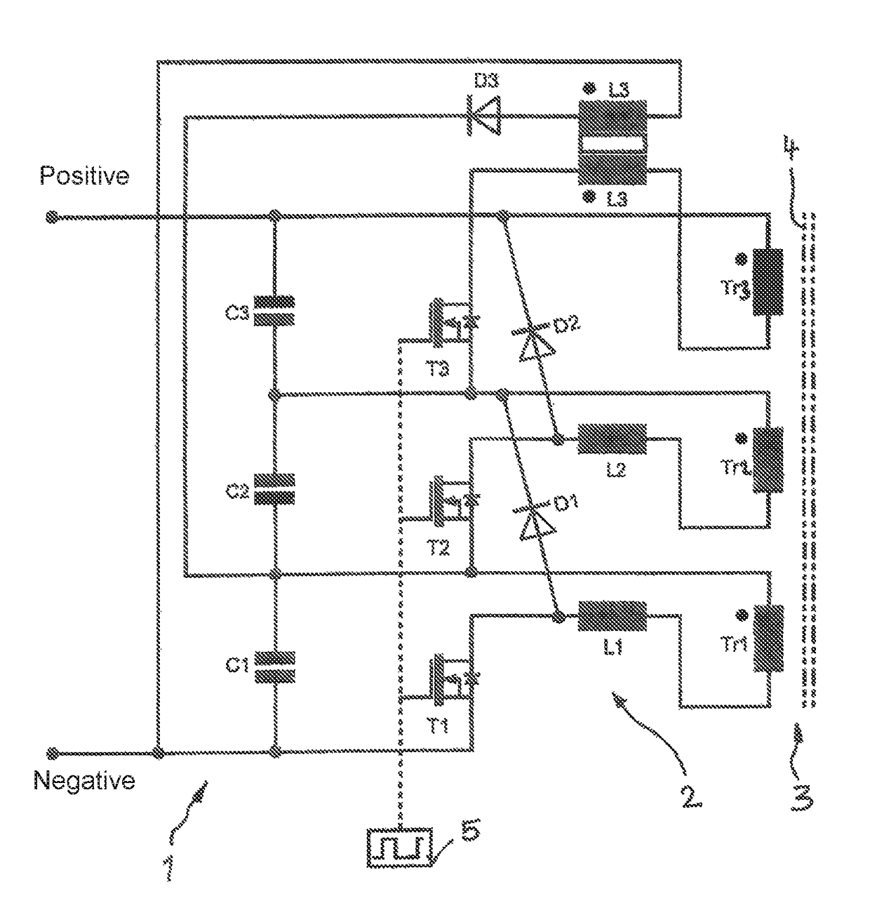
[0037]As FIG. 1 shows, an energy store 1 or an energy storage module can comprise a plurality of storage cells C1, C2 and C3 which are connected in series or serially and which are connected to a common negative pole and to a common positive pole of the energy store 1. The storage cell C1 is in this respect directly connected to the negative pole while the storage cell C3 is disposed closest to the positive pole of the energy store 1.

[0038]Even though FIG. 1 only shows three storage cells C1, C2 and C3, it is understood that the energy store 1 can comprise any desired number, in particular a plurality, of storage cells C1 . . . Cn which are connected in series with one another.

[0039]As FIG. 1 shows, a balun 2 is associated with the storage cells C1, C2 and C3 connected in series and which comprises a balancer transformer 3 which is common to all storage cells and which comprises a number of galvanically separated coils Tr1, Tr2 and Tr3—three in the embodiment of FIG. 1—corresponding...


PUM


Abstract

The present invention relates to an electrical energy storage apparatus having a plurality of electrical storage cells connected in series and to an inductive balun for balancing the storage cell voltages, wherein the balun has a balancer transformer having separate single coils for the storage cells and has a respective electric switch for each storage cell. Provision is made in accordance with the invention that the coils of the balancer transformer are connected to a pole of the respective storage cell via a respective at least one inductance and a switch connected to the named inductance, with the switch associated with one respective storage cell being connected via a diode to a pole of a storage cell respective arranged upstream or downstream.

Description

CROSS REFERENCE TO RELATED APPLICATIONS[0001]The present application is a U.S. National Phase of International Patent Application Serial No. PCT / EP2014 / 003331, entitled “Electrical Energy Storage Device Having a Balancing Circuit,” filed on Dec. 11, 2014, which claims priority to German Patent Application No. 10 2013 021 535.8, filed on Dec. 18, 2013, the entire contents of each of which are hereby incorporated by reference in their entirety for all purposes.TECHNICAL FIELD[0002]The present invention relates to an electrical energy storage apparatus having a plurality of electrical storage cells connected in series and to an inductive balun for balancing the storage cell voltages, wherein the balun has a balancer transformer having separate single coils for the storage cells and has a respective electric switch for each storage cell.BACKGROUND AND SUMMARY[0003]To be able to efficiently operate electrical machines which have highly variable and cyclic power consumption, it is necessa...

Claims


Application Information

Patent Timeline
Patent Type & Authority Patents(United States)
IPC IPC(8): H02J7/00H02J1/00H02M3/335H02M3/06H02J7/34
CPCH02J7/0019H02J7/0016H02J7/345H02J7/00H02J15/00
Inventor SCHUSTER, WOLFGANGWELSER, SVEN
Owner LIEBHERR COMPONENTS BIBERACH GMBH
Why Eureka
Try Eureka