Electromagnetic apparatus for measuring angular position

a technology of angular position and electric field, applied in the direction of resistance/reactance/impedence, devices using electric/magnetic means, instruments, etc., can solve the problems of phase delay or a change in resonant frequency, and achieve the effect of increasing sensitivity, increasing sensitivity, and increasing sensitivity

a technology of angular position and electric field, applied in the direction of resistance/reactance/impedence, devices using electric/magnetic means, instruments, etc., can solve the problems of phase delay or a change in resonant frequency, and achieve the effect of increasing sensitivity, increasing sensitivity, and increasing sensitivity

US20080054911A1Inactive Publication Date: 2008-03-06NYCE DAVID S +1

Image

  • Electromagnetic apparatus for measuring angular position
  • Electromagnetic apparatus for measuring angular position
  • Electromagnetic apparatus for measuring angular position

Examples


Embodiment Construction

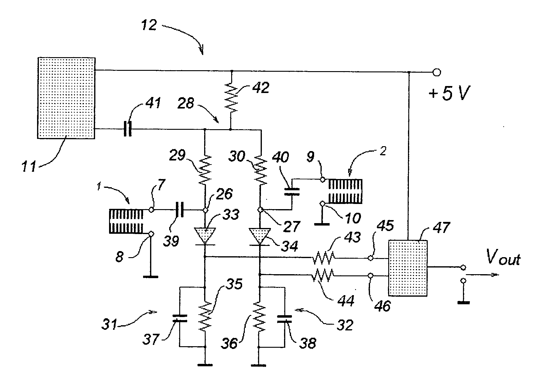
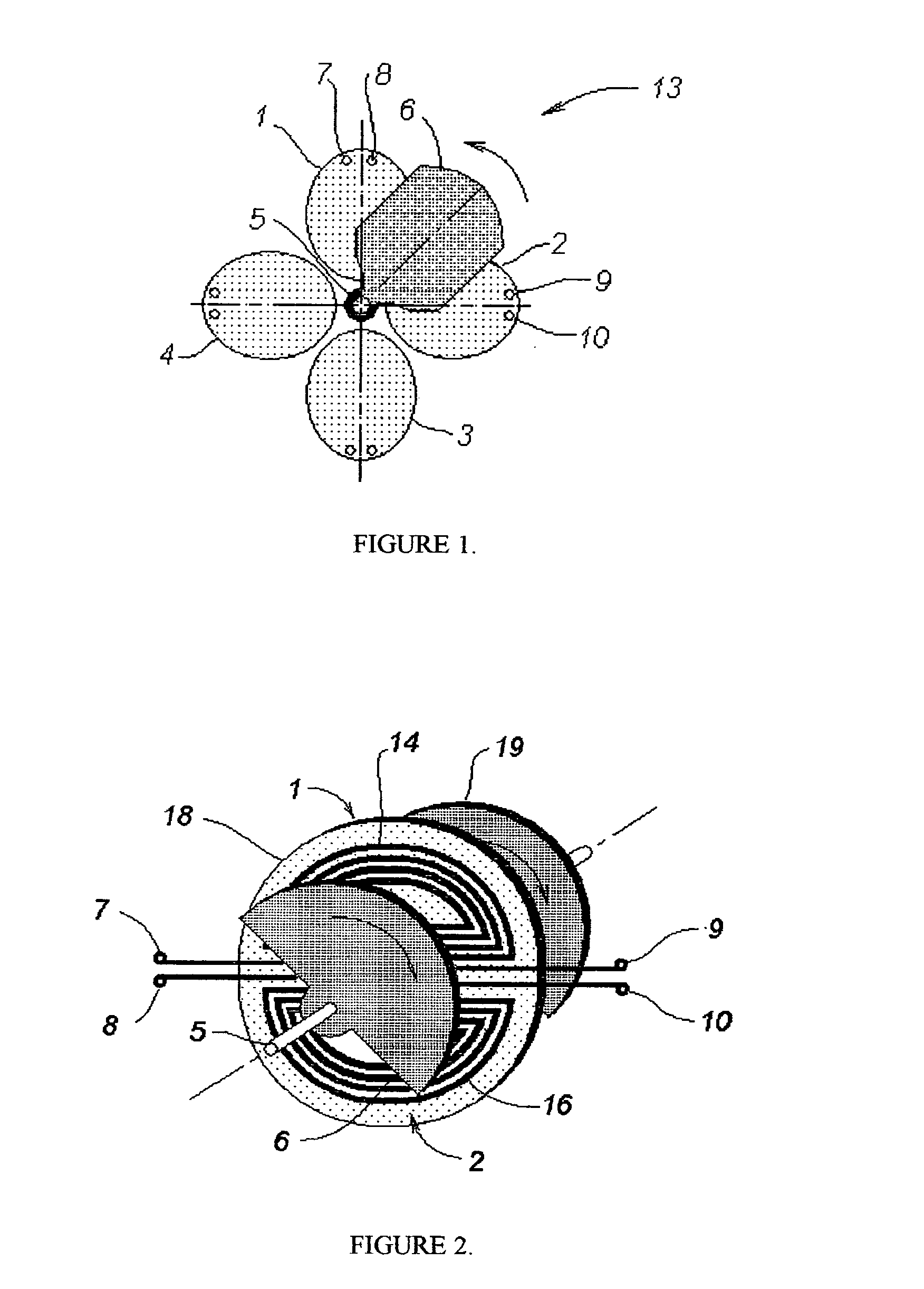
[0026]A general schematic of the present invention is shown in FIG. 1. Here, resonators 1, 2, 3, and 4 are placed in one plane (parallel to the rotation plane) perpendicular to a rotation axis, rotating rod 5. The number of resonators should exceed one. Electrodynamic target 6 connected to rotating rod 5 is installed in a rotation plane, having the capability of beng rotated, and positioned parallel to the plane of the resonators. Its configuration is non-symmetrical with respect to the rotation axis. In all versions of the present invention, electrodynamic target 6 or an additional target positioned on the other side of resonators 1, 2, 3, and 4, should exhibit good electrical conductivity. It can be a metal plate or metallization on a dielectric plate, for example. Terminals of all resonators, e.g. terminals 7 and 8 of resonator 1 and terminals 9 and 10 of resonator 2, are connected to RF oscillator 11 and measuring circuit 12, shown later. All resonators mentioned above are forme...


PUM


Abstract

An apparatus is disclosed for measuring the angular position of a movable part. The method and apparatus comprise at least two resonators formed by coupled slow-wave structures, e.g. coupled spirals, and a movable target. The angular position of the target is representative of the angular position of the movable part. A change in the angular position of the target causes a change in electrodynamic parameters of the resonators. The change in the electrodynamic parameters is converted to a reading of angular position of the target with respect to the resonators. An electromagnetic field is excited in the resonators at a frequency at which electromagnetic parameters of the resonators depend upon the position of the target.

Description

BACKGROUND OF THE INVENTION [0001]1. Field of the Invention[0002]The present invention relates to angular position measurement, more specifically, to an electromagnetic method and apparatus for measuring angular position, rotational speed, or displacement, of a movable target.[0003]2. Description of the Prior Art[0004]The usefulness of the application of an RF or microwave field for the measurement of angular position is recognized by the prior art. Such devices can operate with either RF or microwave excitation. When an electromagnetic field is excited near the rotating part of this type of device, the parameters of the electromagnetic field, such as resonant frequency, phase, or amplitude, vary with a change of angular position of the rotating part. The electromagnetic field parameters may be converted into a desired type of indication, including angle, angular displacement, angular speed, rotation frequency, and so on. In particular, such art is exemplified in U.S. Pat. No. 3,939...

Claims


Application Information

Patent Timeline
06 Mar 2008
Publication
US20080054911A1
IPC
G01R27/32
CPC
G01D5/2225; G01D5/202
Inventors
PCHELNIKOV, YURIY NIKITICH; NYCE, DAVID SCOTT