Intrusion detection system for use on single mode optical fiber using a polarimeter

a detection system and optical fiber technology, applied in the field of single-mode optical fiber detection, can solve the problems of affecting the current idss, burdening processing power, and adding to the complexity of the network

Active Publication Date: 2006-07-13
NETWORK INTEGRITY SYST
View PDF9 Cites 16 Cited by
  • Summary
  • Abstract
  • Description
  • Claims
  • Application Information

AI Technical Summary

Benefits of technology

[0020] It is one object of the present invention to provide an arrangement for detecting movement of an optical fiber which ove

Problems solved by technology

However, this adds to the complexity of the network and burdens processing power.
Current IDSs are hampered by Base-Rate Fallacy limitation, which is the inability to suppress false alarms.
Additionally, software-based IDSs do not provide protection against passive optical fiber tapping, which can go

Method used


Image

  • Intrusion detection system for use on single mode optical fiber using a polarimeter
  • Intrusion detection system for use on single mode optical fiber using a polarimeter
  • Intrusion detection system for use on single mode optical fiber using a polarimeter

Examples


Embodiment Construction

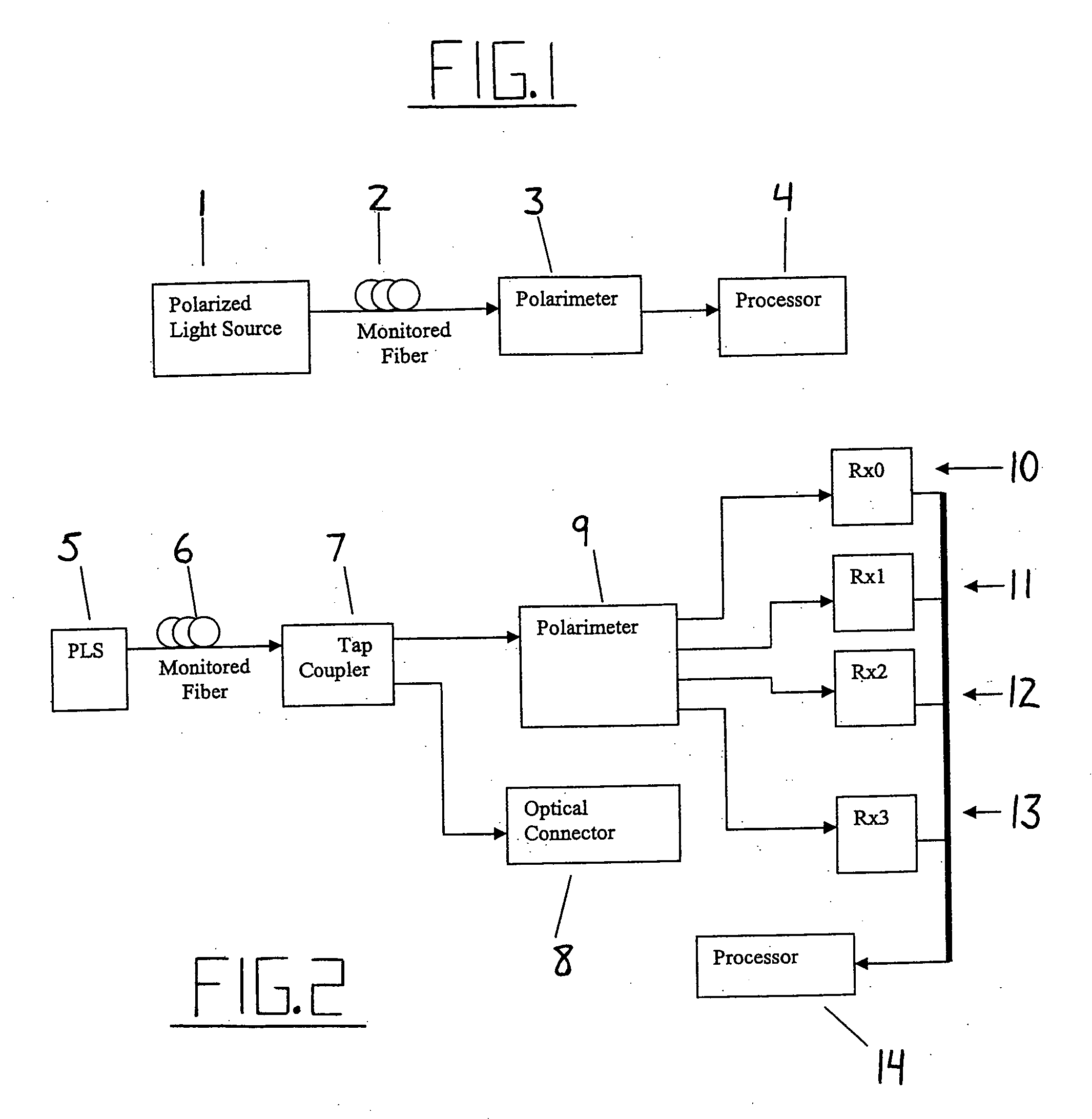
[0079] Fundamental to the present invention is the mechanics or more simply by launching a light source of stable polarization 1 into a single mode fiber 2. At the remote or receive end the single mode fiber is connected to the input of an optical polarimeter 3. This polarimeter measures the SOP of the monitored light. The output of this polarimeter is connected to a processor unit 4; such as, but not limited to, a microcomputer. Handling of the fiber cable causes a local mechanical disturbance to the fiber. This mechanical disturbance, while not introducing detectable macro or micro bending losses, causes the polarization orientation to change. This is detected by the polarimeter and reported to the processor.

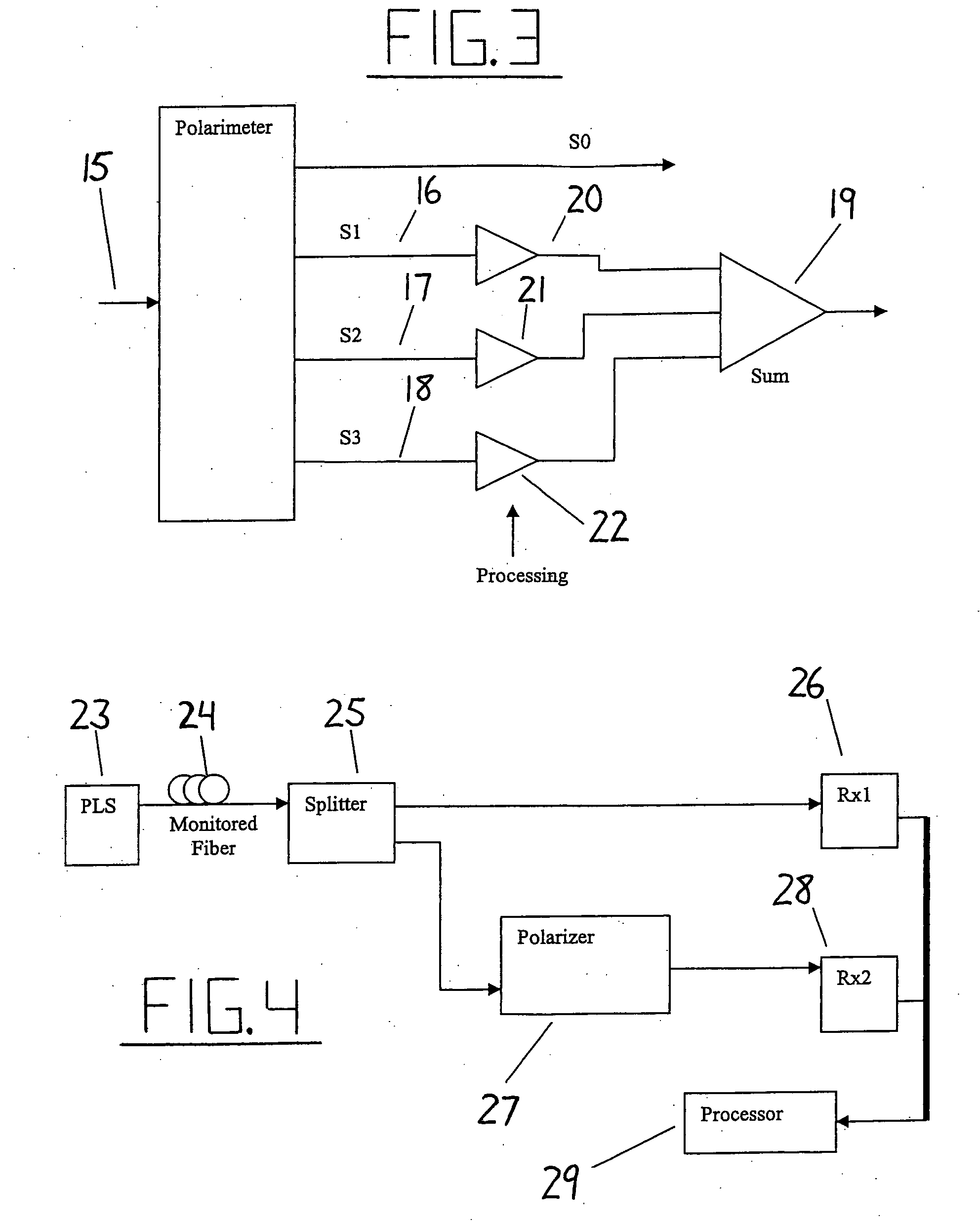
[0080] A more comprehensive view is now described in conjunction with FIG. 2. Optical signal feeds the polarimeter 9, which converts it to the four so-called Stokes Parameters: S0, S1, S2, and S3 as detected by receivers Rx0-Rx310, 11, 12, and 13. These parameters collectivel...


PUM


Abstract

A telecommunications optical fiber is secured against intrusion by detecting manipulation of the optical fiber prior to an intrusion event. This can be used in a non-locating system where the detection end is opposite the transmit end or in a locating system which uses Fresnel reflections and Rayleigh backscattering to the transmit end to detect and then locate the motion. The Rayleigh backscattering time sliced data can be stored in a register until an intrusion event is detected. The detection is carried out by a polarization detection system which includes an optical splitter which is manufactured in simplified form for economic construction. This uses a non-calibrated splitter and less than all four of the Stokes parameters. It can use a polarimeter type function limited to linear and circular polarization or two linear polarizers at 90 degrees.

Description

RELATED APPLICATIONS [0001] This application claims priority under 35 U.S.C. 119 from Provisional Applications 60 / 643,001, 60 / 643,002, 60 / 643,003 and 60 / 643,004 all filed Jan. 12th 2005. [0002] Reference is made to co-pending applications filed on the same date as this application by the same inventors, the disclosures of which are incorporated herein by reference as follows: [0003] Application Serial No. (not yet known) attorney docket number 85570-302 entitled AN INTRUSION DETECTION SYSTEM FOR USE ON SINGLE MODE OPTICAL FIBER USING FRESNEL REFLECTIONS. [0004] Application Serial No. (not yet known) attorney docket number 85570-332 entitled AN INTRUSION DETECTION SYSTEM FOR USE ON SINGLE MODE OPTICAL FIBER USING A STORAGE REGISTER FOR DATA. [0005] Application Serial No. (not yet known) attorney docket number 85570-232 entitled AN INTRUSION DETECTION SYSTEM FOR USE ON SINGLE MODE OPTICAL FIBER USING A SIMPLIFIED POLARIMETER. [0006] Application Serial No. (not yet known) attorney dock...

Claims


Application Information

Patent Timeline
IPC IPC(8): G02B6/00
CPCG02B6/276H04B10/071H04B10/532H04B10/85H04L63/1416G08B13/186G08C23/06
Inventor MURPHY, CARY R.VOKEY, DAVID E.BRIDGES, MARK K.
Owner NETWORK INTEGRITY SYST
Why Eureka
Try Eureka