Collapsed mode capacitive sensor

a capacitive sensor and capacitive sensor technology, applied in the field of capacitive sensors in collapsed mode, can solve the problems of difficult to achieve high sensitivity and low noise with very small volumes, time-consuming and costly process, and difficult to achieve all of these characteristics in microphones under 1 mm in size using integrated circuit materials, etc., to achieve the effect of improving functionality

Inactive Publication Date: 2012-05-31
NXP BV
View PDF5 Cites 20 Cited by
  • Summary
  • Abstract
  • Description
  • Claims
  • Application Information

AI Technical Summary

Benefits of technology

[0007]It is an objective of the presented invention to

Problems solved by technology

However, it is difficult to achieve high sensitivity and low noise with very small volumes.
Further, a conventional silicon capacitive microphone always needs through-wafer etching to create separation of the

Method used


Image

  • Collapsed mode capacitive sensor
  • Collapsed mode capacitive sensor
  • Collapsed mode capacitive sensor

Examples


Embodiment Construction

[0020]The present invention is further elucidated by the following figures and examples, which are not intended to limit the scope of the invention. The person skilled in the art will understand that various embodiments may be combined.

BRIEF DESCRIPTION OF THE DRAWINGS

[0021]It is an objective of the presented invention to provide a capacitive sensor with improved functionality.

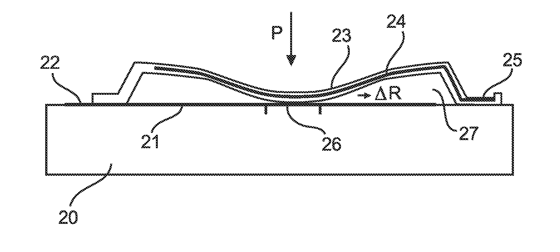
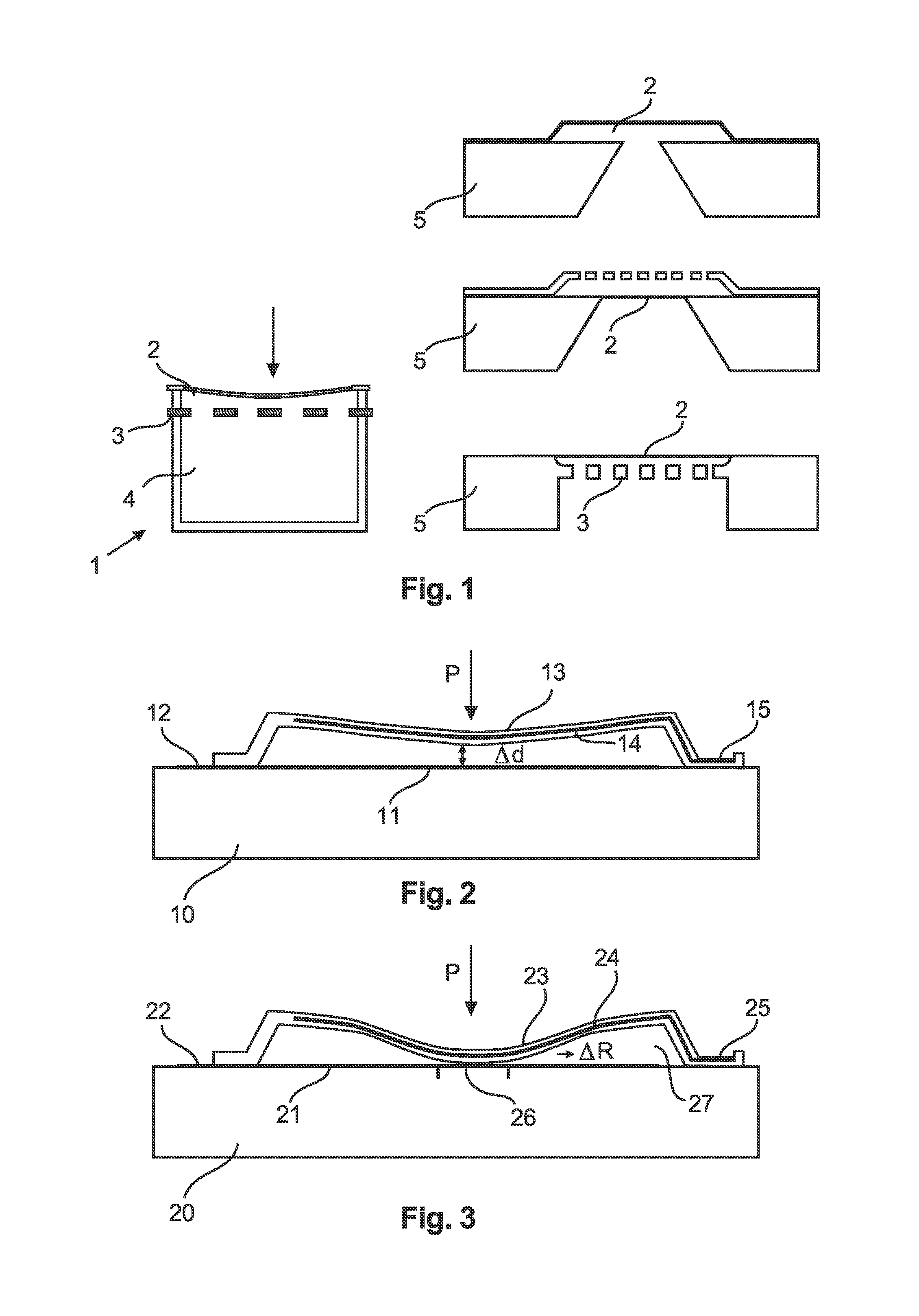
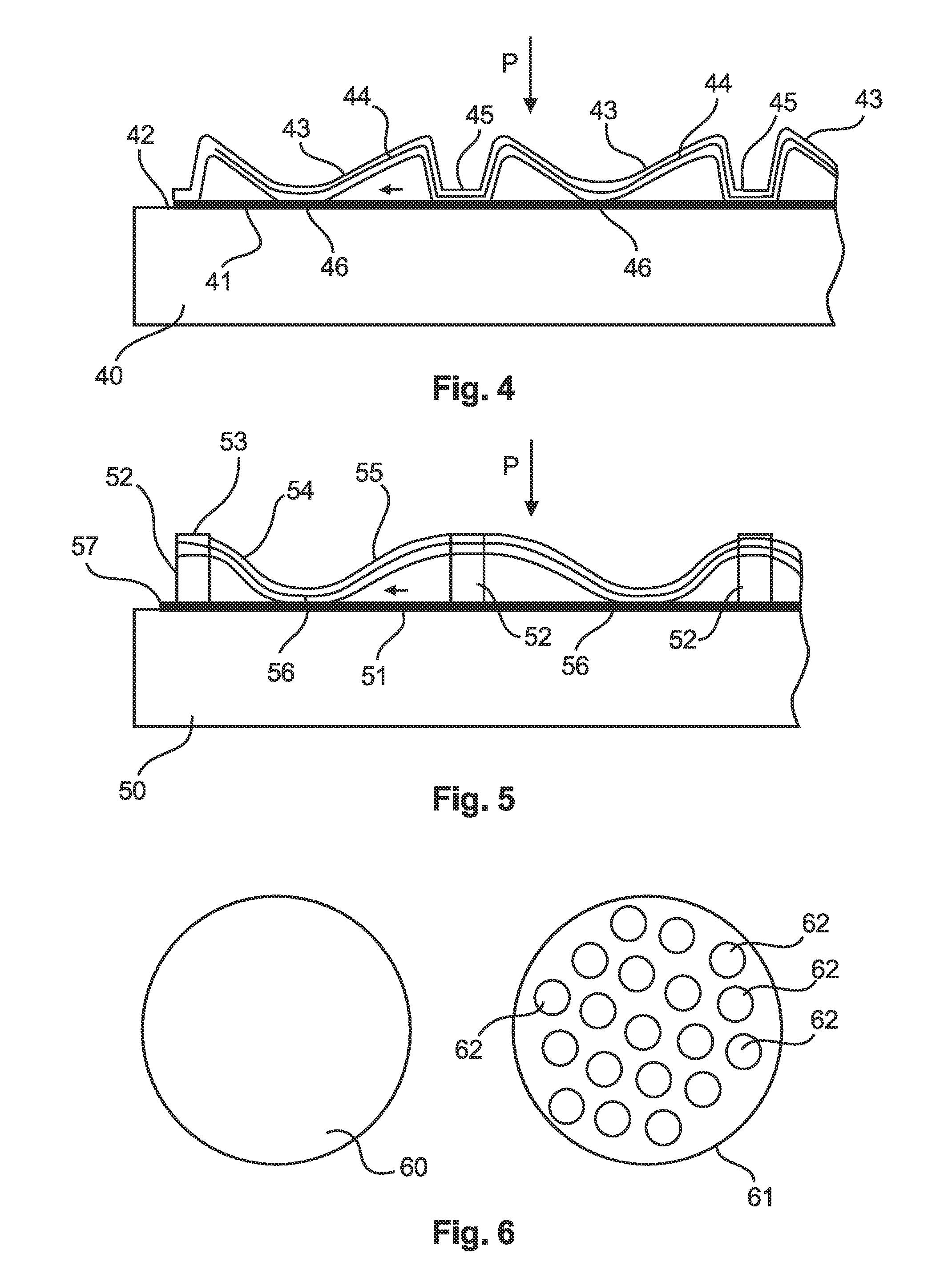
[0022]In accordance with one or more of the embodiments a capacitive sensor is provided for measuring a physical parameter such as sound or pressure. The sensor may comprise a moveable membrane forming an upper electrode, and a bottom layer forming a bottom electrode, wherein the sensor is configured to be driven in a collapsed mode in which the moveable membrane is brought into contact with the bottom layer. The magnitude of the area of contact between the moveable membrane and the bottom layer is configured to depend on the physical parameter to be measured such as the strength and / or frequency of the physic...


PUM


Abstract

A capacitive sensor is configured for collapsed mode, e.g. for measuring sound or pressure, wherein the moveable element is partitioned into smaller sections. The capacitive sensor provides increased signal to noise ratio.

Description

FIELD OF THE INVENTION[0001]The present invention generally relates to devices, methods, and programs of or for capacitive sensing such as electroacoustic transducers, for example ultrasound devices suitable for example for physiological measurement, or pressure sensors, etc.BACKGROUND OF THE INVENTION[0002]Generally, miniature silicon condenser microphones such as capacitive MEMS, micro-electrical-mechanical system, microphones can be integrated with CMOS circuitry and can be produced by batch processing which makes the device to device variation much smaller. Further, miniature silicon condenser microphones have a form factor compatible with state-of-the-art hand held device architectures, and do not need an electret for electrical biasing which makes them easier to solder onto a printed circuit board, PCB, than conventional electret microphones.[0003]However, it is difficult to achieve high sensitivity and low noise with very small volumes. Further, a conventional silicon capacit...

Claims


Application Information

Patent Timeline
IPC IPC(8): H01L29/84H01L21/00H01L29/40
CPCB06B1/0292G01L9/0072H04R31/006H04R19/04H04R7/12
Inventor LANGERIES, GEERTVAN LIPPEN, TWANWOLTJER, REINOUT
Owner NXP BV
Why Eureka
Try Eureka