Cryogenic fiber optic temperature sensor and method of manufacturing the same

a fiber optic temperature sensor and fiber optic technology, applied in the field of fiber optic sensors temperature sensors, can solve the problems of poor multiplexing capability, inability to meet the required resolution and accuracy at cryogenic temperatures, and inability to multiplex multiplexable fiber optic temperature sensing solutions, etc., to achieve the effect of increasing the sensitivity of the sensor, easy manufacturing, and multi-plexibility

Inactive Publication Date: 2011-11-17
KOCHERGIN VLADIMIR
View PDF12 Cites 18 Cited by
  • Summary
  • Abstract
  • Description
  • Claims
  • Application Information

AI Technical Summary

Benefits of technology

[0009]It is an object of the present invention to provide a new design fiber optic temperature sensor that would provide practical levels of sensitivity at cryogenic temperature range (down to 2K or below) and will be multiplexible, inexpensive and easy to manufacture. It is another object of the present invention to provide a practical method of fabrication of fiber optic temperature sensors for cryogenic temperature range.
[0010]According to the first embodiment of the present invention the fiber optic temperature sensor comprises the optical fiber for carrying an optical signal, the optical fiber having: a length, a thermal expansion coefficient, at least one core and at least one cladding, the sensor further comprising: at least one grating associated with the core of the optical fiber at a location along the length of the optical fiber, the grating for selectively altering portions of the signal carried by the optical fiber; and a coating integrated with the cladding at the location, the coating for increasing the sensitivity of the sensor to changes in temperature at the location, the coating having a thermal expansion coefficient that is smaller than the thermal expansion coefficient of the optical fiber but larger in absolute value than the thermal expansion coefficient of the optical fiber at least over a range of temperatures. It is further preferable that the sign of the thermal expansion coefficient is changing from positive to negative at some temperature between the cryogenic temperature range (which is understood to be 77K or below) and room temperature. In such a realization the disclosed fiber optic temperature sensor will have significant sensitivity at cryogenic temperature range (due to much higher absolute value of thermal expansion coefficient of the coating compared to that of silica) while the delamination / fiber breakage issues will be resolved due to minimized stress in the interface of the silica and coating due to change of sign of CTE of the coating between the room temperature and the cryogenic temperature. According to one illustrative example, the coating material may comprise the composite consisting of CuO nanoparticles with diameters in the 2 nm to 15 nm range dispersed in epoxy resin host, further denoted as a composite of the present invention. According to another illustrative example, the coating material may comprise the composite consisting of nanoparticles of antiperovskite-structured material dispersed in epoxy resin, said antiperovskite-structured material being selected from the group consisted of Mn3CuN and Mn3ZnN, said antiperovskite-structured material being doped by the chemical element selected from the group consisted of Ge, Sn, Ga, Nb, Si.
[0011]According the second embodiment of the present invention the fiber optic temperature sensor of the present invention comprises Rayleigh scattering-based sensor, which comprises, the optical fiber for carrying an optical signal, said optical fiber having a length, a thermal expansion coefficient, at least one core and at least one cladding, the sensor further comprising at least one section of the optical fiber at a location along the length of the optical fiber; and a coating integrated with the cladding at the location of said section, the coating for increasing the sensitivity of the sensor to changes in temperature at the location, the coating having a thermal expansion coefficient that is smaller than the thermal expansion coefficient of the optical fiber but larger in absolute value than the thermal expansion coefficient of the optical fiber at least over a range of temperatures.

Problems solved by technology

Electronic temperature sensors (typically resistors or diodes of various types, less often thermocouples) while offering proven solution, have a number of deficiencies originating from poor multiplexing capability of such sensors as well as sensitivity to the magnetic fields.
However, to date highly multiplexible fiber optic temperature sensing solutions were unable to meet the required levels of resolution and accuracy at cryogenic temperatures.
Fluorescence lifetime-based fiber optic temperature sensors are the exception; however, such sensors are poorly multiplexible.
While such a solution indeed showed improved levels of temperature resolution at cryogenic temperatures, it possessed two major deficiencies: 1) CTE of these materials is still significantly diminishes as temperature approaches ˜20K, 2) Significantly different CTEs of silica core of the fiber and the coating with a thermal expansion coefficient that is larger than the thermal expansion coefficient of the optical fiber are causing significant stress on the interface between the fiber and the coating.
These stresses are often causing delamination of the coating and / or breakage of the fiber.

Method used


Image

  • Cryogenic fiber optic temperature sensor and method of manufacturing the same
  • Cryogenic fiber optic temperature sensor and method of manufacturing the same
  • Cryogenic fiber optic temperature sensor and method of manufacturing the same

Examples


Embodiment Construction

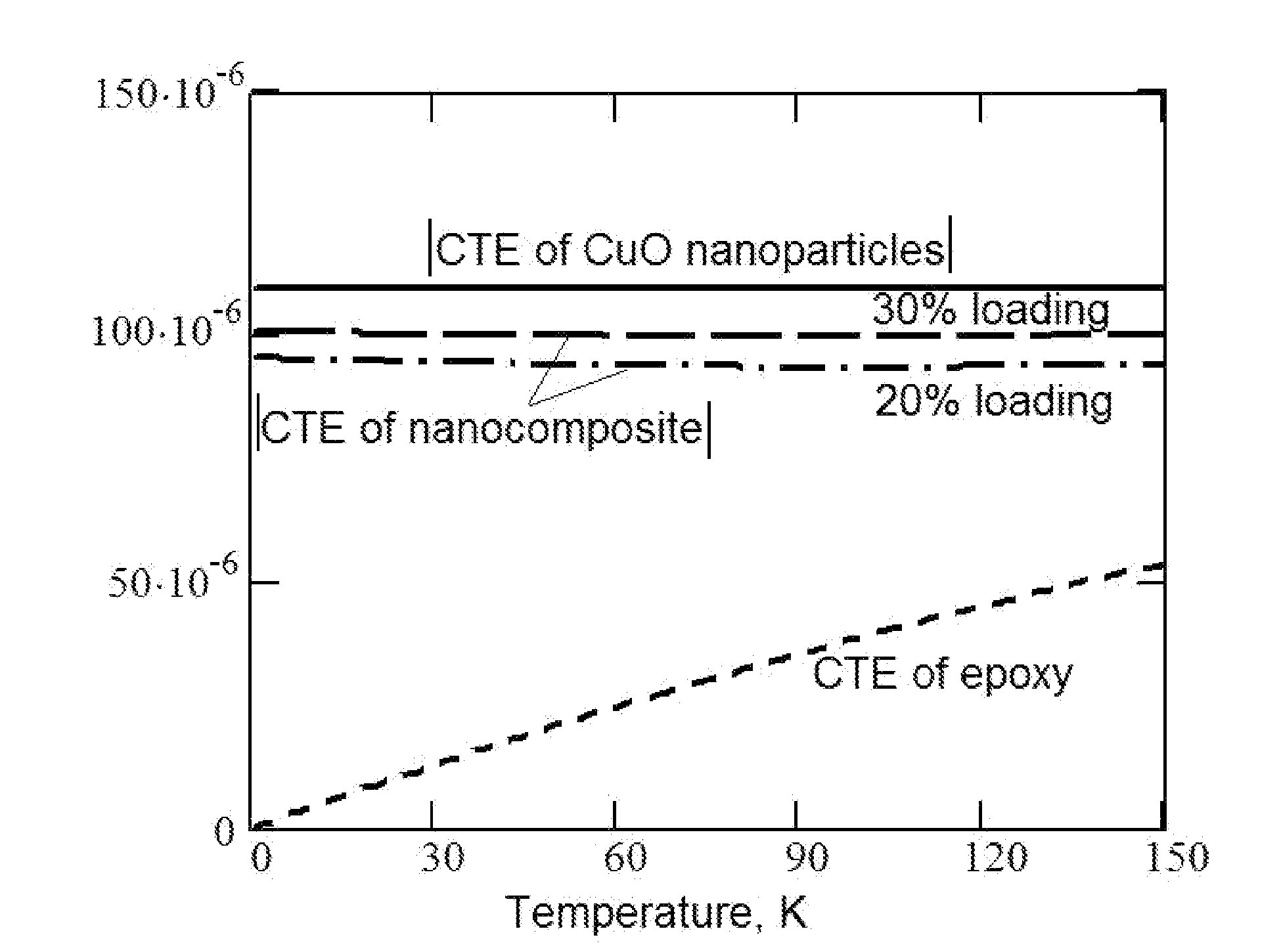
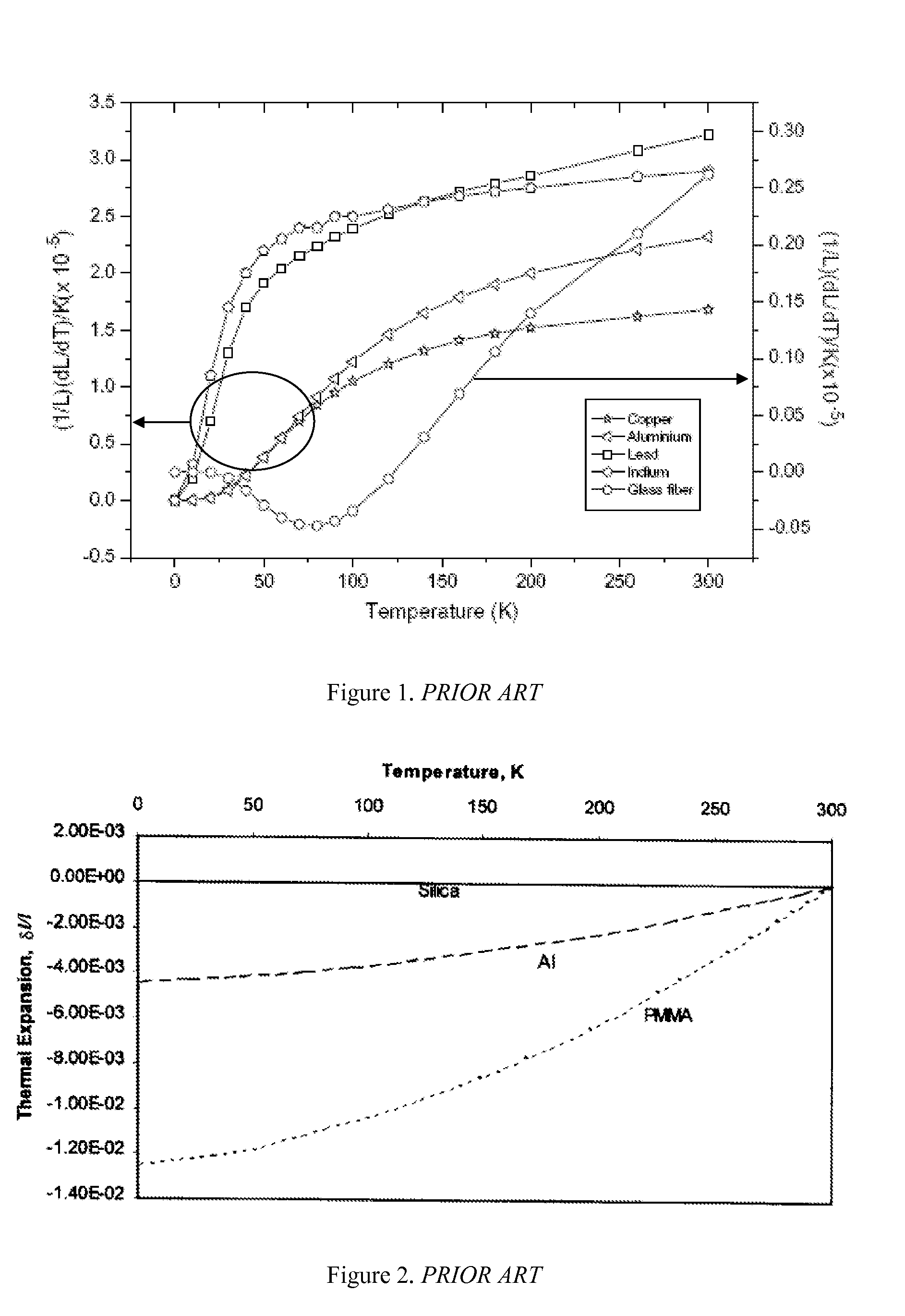
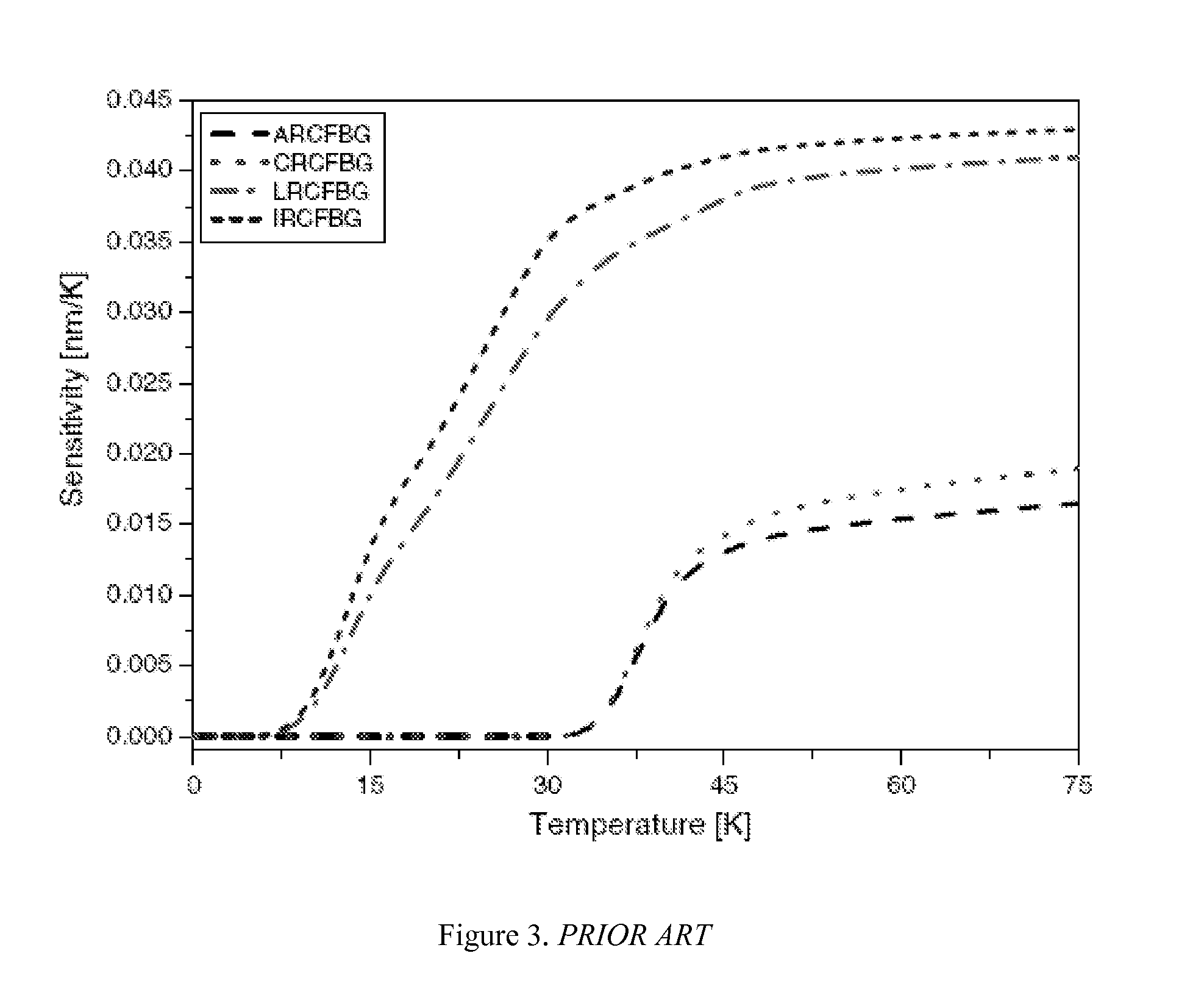
[0023]According to the present invention, a fiber optic temperature sensor for cryogenic temperature range is provided, wherein the optical fiber is coated with the coating that exhibits a thermal expansion coefficient that is lower than the thermal expansion coefficient of the optical fiber but higher in absolute value than the thermal expansion coefficient of the optical fiber at least over a range of temperatures for increasing the sensitivity of the sensor to changes in temperature at the location. Said coating is preferably having negative thermal expansion coefficient over a range of temperatures. It is further preferable that the sign of the thermal expansion coefficient is changing from positive to negative at some temperature between the cryogenic temperature range (which is understood to be 77K or below) and room temperature. In such a realization the disclosed fiber optic temperature sensor will have significant sensitivity at cryogenic temperature range (due to much high...


PUM

PropertyMeasurementUnit
diametersaaaaaaaaaa
diametersaaaaaaaaaa
cryogenic temperaturesaaaaaaaaaa

Abstract

This invention teaches the fiber optic sensors temperature sensors for cryogenic temperature range with improved sensitivity and resolution, and method of making said sensors. In more detail, the present invention is related to enhancement of temperature sensitivity of fiber optic temperature sensors at cryogenic temperatures by utilizing nanomaterials with a thermal expansion coefficient that is smaller than the thermal expansion coefficient of the optical fiber but larger in absolute value than the thermal expansion coefficient of the optical fiber at least over a range of temperatures.

Description

STATEMENT REGARDING FEDERALLY SPONSORED RESEARCH OR DEVELOPMENT[0001]This invention was made with Government support under contracts NNX10CD42P awarded by NASA and DE-SC0001964 awarded by DoE. The Government has certain rights in this invention.CROSS-REFERENCES TO RELATED APPLICATIONS[0002]Not applicable.FIELD OF THE INVENTION[0003]The present invention relates to fiber optic sensors temperature sensors for cryogenic temperature range and method of making the same. In more detail, the present invention is related to enhancement of temperature sensitivity of fiber optic temperature sensors at cryogenic temperatures by utilizing nanomaterials with enhanced values of thermal expansion coefficients at cryogenic temperatures.BACKGROUND OF THE INVENTION[0004]A number of applications require temperature measurements in a number of different spatial locations at cryogenic temperatures (below 77K). These include superconductive cavity characterization for particle accelerators, superconducti...

Claims


Application Information

Patent Timeline
Patent Type & Authority Applications(United States)
IPC IPC(8): G01K11/32
CPCG01K2203/00G01K11/32
Inventor KOCHERGIN, VLADIMIR
Owner KOCHERGIN VLADIMIR
Why Eureka
Try Eureka