Temporary closure

a technology of temporary closures and closures, applied in the field of temporary closures, can solve the problems of specific coverings, unauthorized persons quickly and easily gaining entry into the building, and relatively high manufacturing costs, and achieve the effect of simple and inexpensive design and easy chang

Active Publication Date: 2006-08-10
LASSE RAMSKOV HLDG
View PDF20 Cites 9 Cited by
  • Summary
  • Abstract
  • Description
  • Claims
  • Application Information

AI Technical Summary

Benefits of technology

[0010] The invention relates to a temporary closure that has a simple and inexpensive design. In addition, this temporary closure is easy to mount and demount. This temporary closure is adaptable in that its size can easily be changed within a larger interval than previously known constructions. Also, the temporary closure can be arranged to secure a structural opening against passage of unauthorized persons.

Problems solved by technology

However, these temporary closures are relatively expensive to manufacture, as they have to be manufactured individually to be adapted to structural openings of different dimensions and tolerances.
Another disadvantage is that unauthorized persons quickly and easily could gain entry to the building by merely cutting the sheet open with a knife.
However, it is a problem that a specific covering must be made for each size.
Thereby, the frame will be expensive to adapt in size.
It is a problem that a specific sheet must be manufactured for each size.
The pane is automatically fixed in the frame by means of a complicated and expensive assembly of said springs and foam rubber strips which however only allow a change in size that is exactly enough to mount and demount the temporary window in the above manner.
These operations are furthermore very hard and difficult to perform because it is necessary during this to press all four sides inwards at the same time.

Method used


Image

  • Temporary closure
  • Temporary closure
  • Temporary closure

Examples


second embodiment

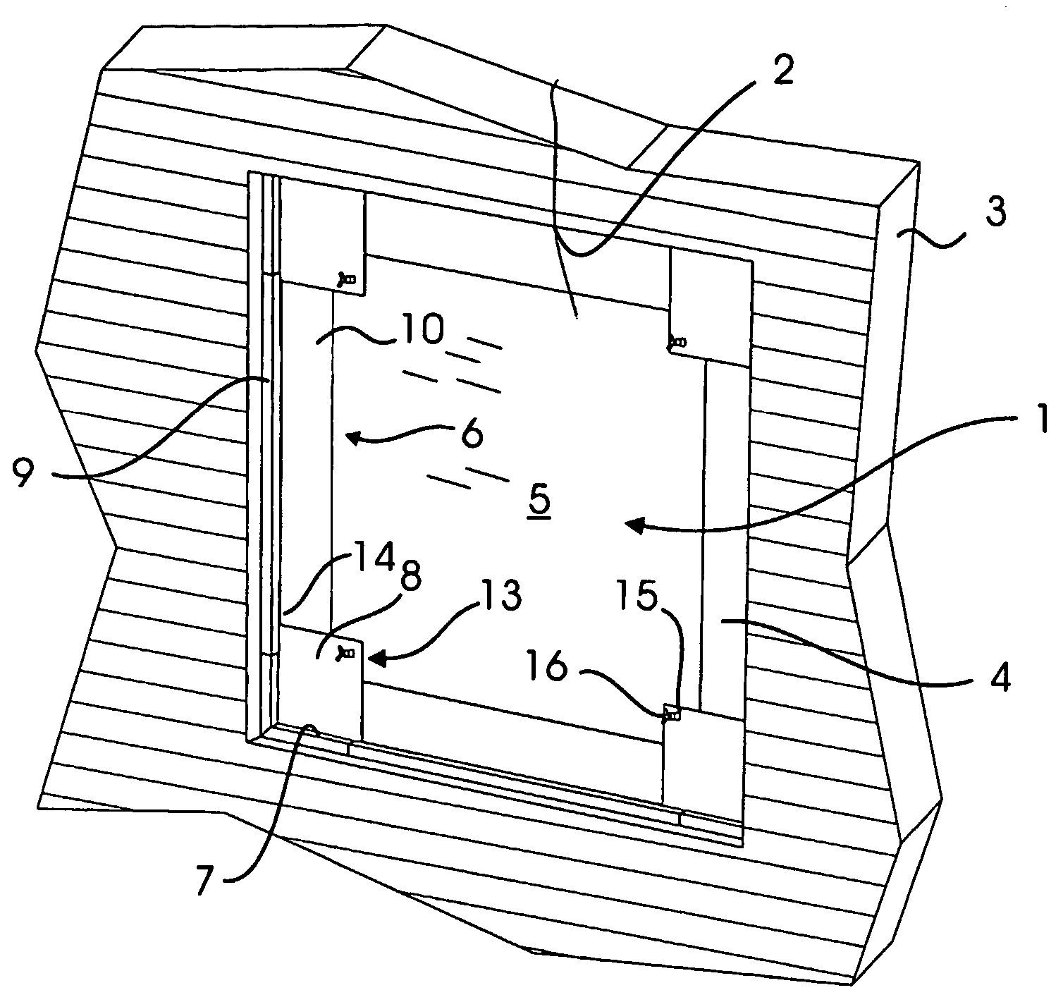
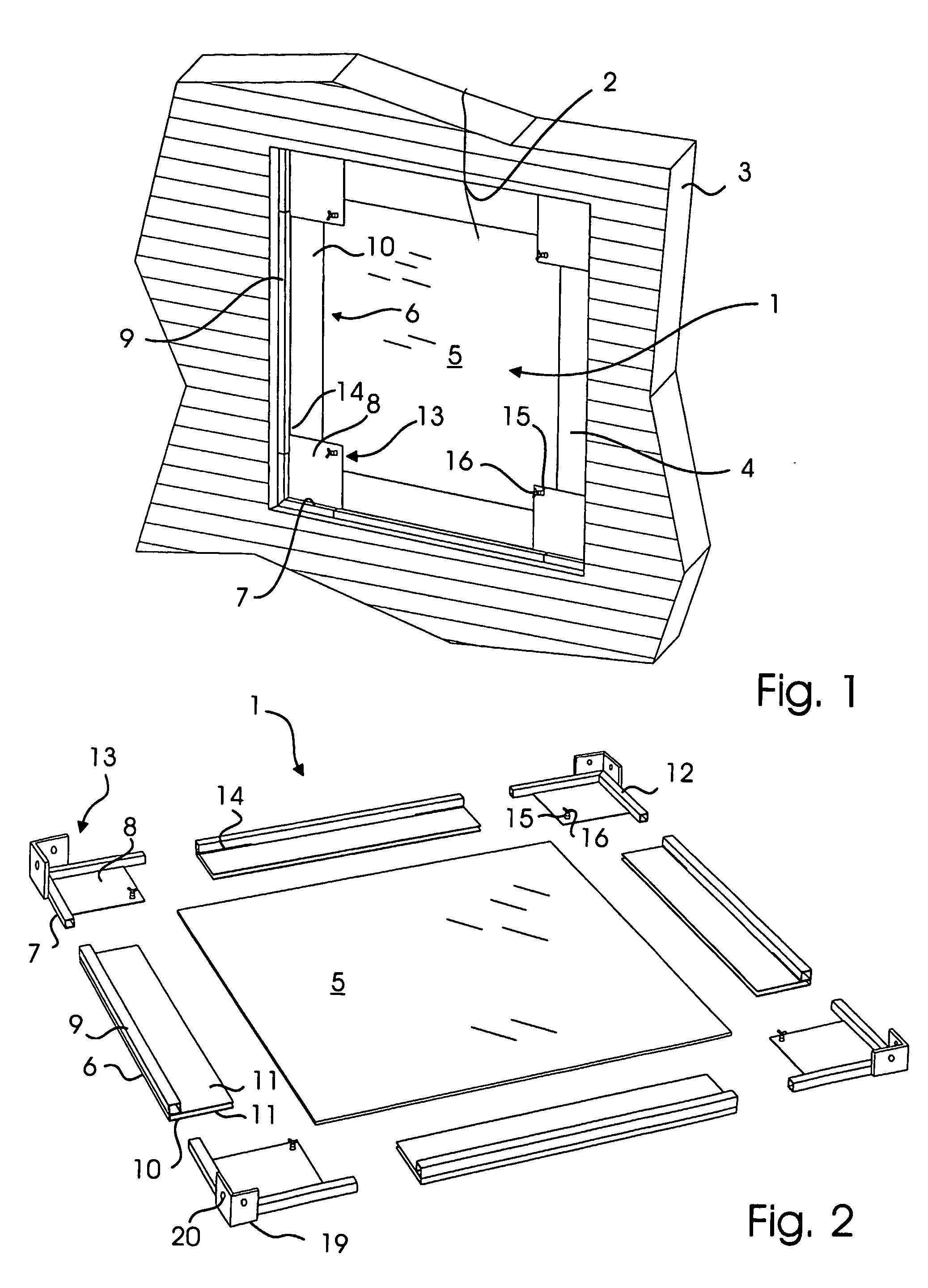
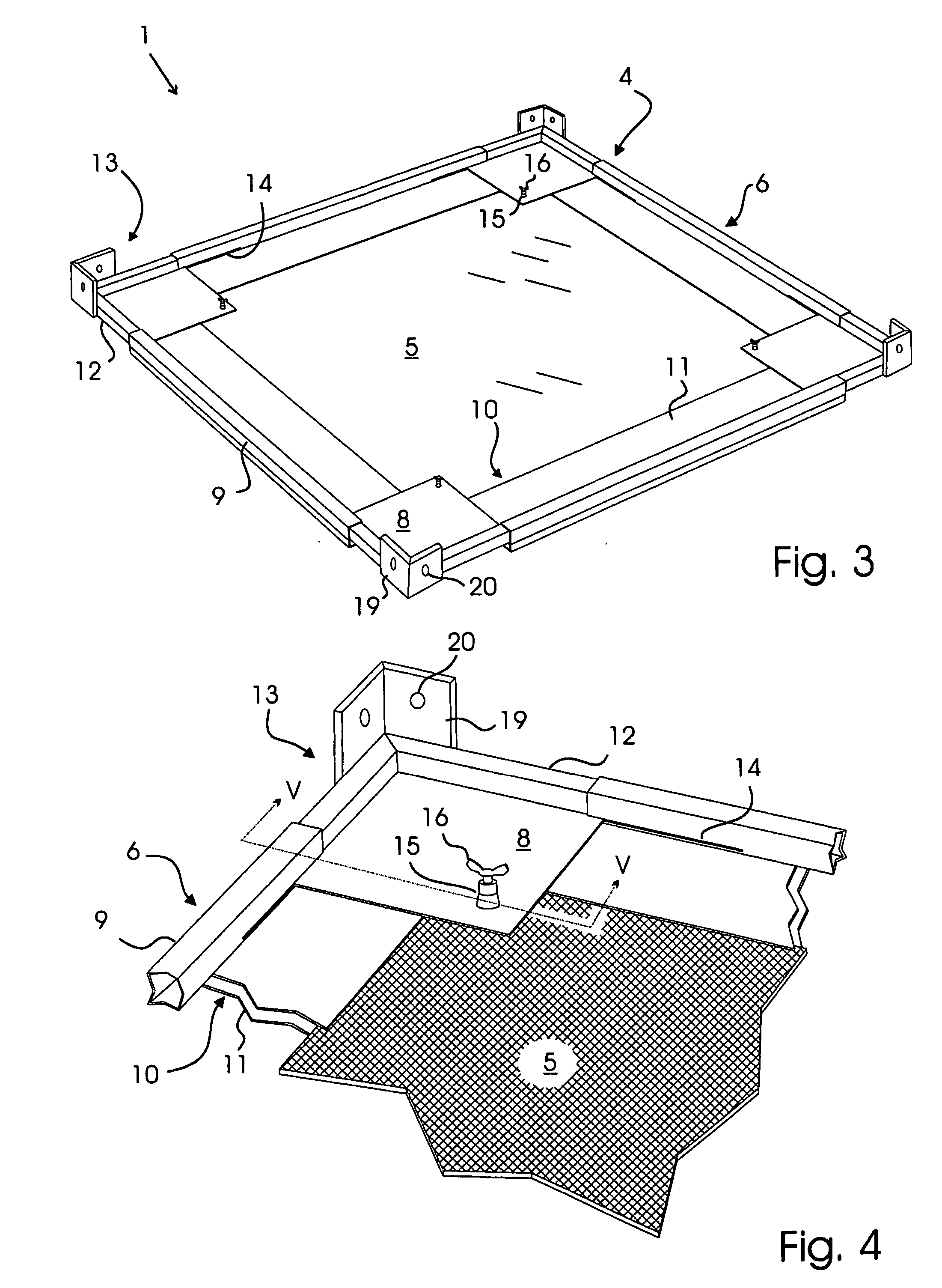
[0038] The fastener may be a nut 15 is mounted with a flap screw 16 to be tightened in towards the pane and thereby quickly and easily fix this pane in a relatively central position in the frame. FIG. 5 is a cross sectional view of one embodiment of the screw 16. In this case, the screw is made with a point 17 which is forced a little into the pane upon tightening. This embodiment of the screw is well suited to fix the pane in position in the frame if it is made of a relatively soft material, for example plastic. FIG. 6 is a cross sectional view of the screw 16 which, in this case, is provided with a foot 18 of an elastomeric material, for example rubber. This embodiment of the screw is well suited to fix the pane in position in the frame if the pane is made of a relatively hard material, for example glass.

[0039]FIGS. 4, 5, and 6 also show a mounting fitting 19 that is fastened on the corner 13 of the frame. The mounting fitting is made with holes 20 for screws or bolts (not shown) ...

fourth embodiment

[0043] As shown in FIGS. 9 and 10, the temporary closure can, in a fourth embodiment, be formed as a temporary door assembly 24 to fit in a door opening. The door assembly 24 comprises a door 25 and a doorframe 26. The door 25 is, among other things, made up of side members 27, corner members 28, and corner plates 29 joined in the same way as described above and with two mounting plates 30 provided on each side member 27 to secure a pane 31 of glass or another material, such as for example a wooden board or polycarbonate. And as described in previous embodiments, the pane is furthermore fixed by means of flap screws 32 formed on the corner plates 29.

[0044] The doorframe 26 comprises two angular frame members 33 joined via a telescopic member 34 by means of a first clamping nut 35 on each frame member 33. In the opposite end of each frame member, a frame base 36 is mounted which also is telescopically fastened to each frame member by means of a second clamping nut 37. Thus, the doorf...


PUM


Abstract

A temporary closure with a solid pane of for example glass framed in a quadrangular frame that includes four side members forming at least a part of each their side of the frame sides; eight corner members each telescopically connected to a side member and in pairs forming the four corners of the frame; four longitudinal mountings fastened on each their side member and each arranged to displaceably receive an area of the pane, and a fastener for fixing the pane in a wanted position in the frame. The frame includes at least one corner plate fastened on each of the corners of the frame and having sides that are longer than the extent of the adjacent mounting in the transverse direction. The temporary closure can be mounted and demounted quickly and easily, and its size can be changed to adapt to an opening. The temporary closure gives good security against the intrusion of unauthorized persons, as the solid pane cannot easily be broken through or cut open in the same way as panes consisting of a flexible plastic sheet.

Description

CROSS-REFERENCE TO RELATED APPLICATION [0001] This application is a continuation of International application PCT / DK2004 / 000656 filed Sep. 29, 2004, the entire content of which is expressly incorporated herein by reference.BACKGROUND ART [0002] The invention relates to a temporary closure with a solid pane of e.g. glass framed in a quadrangular frame comprising four side members each forming at least a part of each their side of the frame, eight corner members each telescopically connected to a side member and in pairs forming the four corners of the frame, four longitudinal mountings mounted on each their side member and each arranged to displaceably receive an area of the pane, and means for fixing the pane in a wanted position in the frame. [0003] In buildings that are being built, rebuilt or renovated, there are often a number of structural openings that must be closed temporarily to keep out rain, snow and wind, and during the cold period of the year furthermore keep the heat i...

Claims


Application Information

Patent Timeline
Patent Type & Authority Applications(United States)
IPC IPC(8): E06B3/26E04G21/24E06B3/70E06B3/92E06B5/02
CPCE04G21/24E06B3/92E06B5/025E06B2003/7096E04G21/241E04G21/28E06B5/02
Inventor HANSEN, SORENJENSEN, LASSE RAMSKOV
Owner LASSE RAMSKOV HLDG
Why Eureka
Try Eureka