Hydraulic mount apparatus for supporting vibration source

a technology of vibration source and hydraulic mount, which is applied in the direction of damper-spring combination, spring/damper, shock absorber, etc., can solve the problems of reducing the service life of the system, limiting the isolating capacity of vibration source, etc., and achieves low cost, simple design, and minimize the mass of the apparatus

Active Publication Date: 2016-04-26
BEIJING WEST IND CO LTD
View PDF26 Cites 9 Cited by
  • Summary
  • Abstract
  • Description
  • Claims
  • Application Information

AI Technical Summary

Benefits of technology

[0010]Thus several advantages of one or more aspects of the invention are that the hydraulic mount apparatus is able to substantially cancel vibrations at relatively low frequencies through the magnetorheological fluid-based damping components as well as high frequencies through the actuator and moving member while minimizing the mass of the apparatus since a secondary mass and piezostack actuator do not need to be sized relative to external excitations. Accordingly, the invention provides for an inexpensive, simple design that provides for the cancellation of external excitation at a wide range of frequencies.

Problems solved by technology

A common shortcoming of magnetorheological fluid-based mounts is that their vibration isolating capabilities are limited to isolating vibrations at relatively low frequencies, typically less than approximately 20 Hz, because the magnetorheological fluid is unable to pass through the fluid passage at higher frequencies.
However, a downside to this system is that the secondary mass and piezostack actuator have to be sized properly in order to cancel the forces from the external excitation, resulting in the addition of undesirable extra mass to the system.

Method used


Image

  • Hydraulic mount apparatus for supporting vibration source
  • Hydraulic mount apparatus for supporting vibration source

Examples


Embodiment Construction

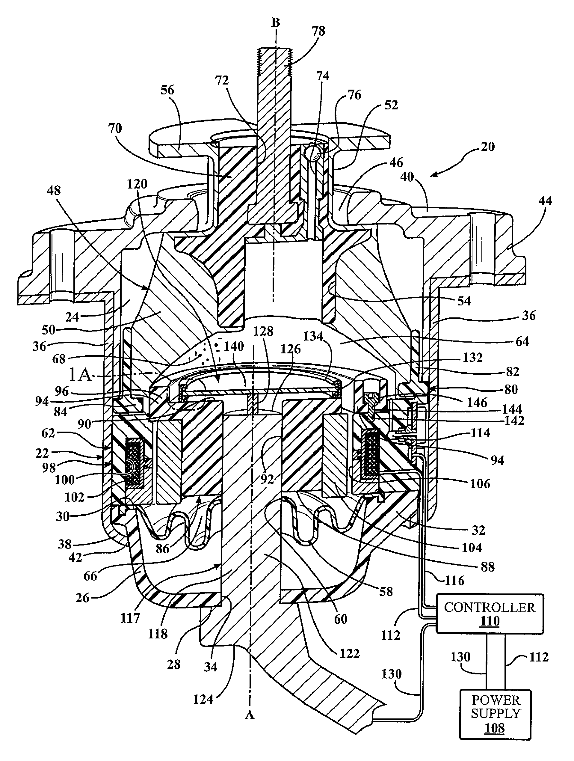
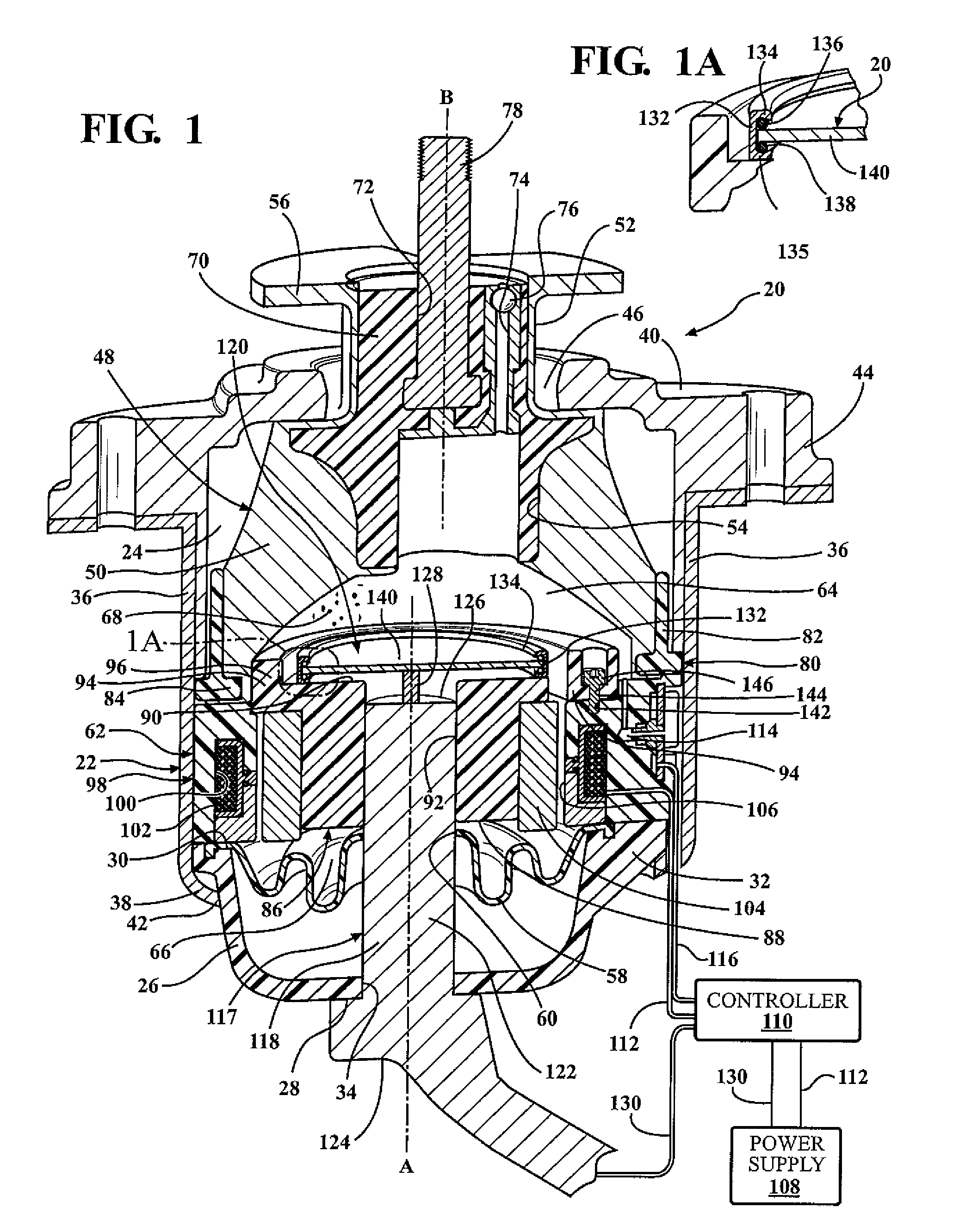
[0014]Referring to the Figures, wherein like numerals indicate corresponding parts throughout the several views, a hydraulic mount apparatus 20 is generally shown for supporting a vibration source on a base. In the enabling embodiment the hydraulic mount apparatus 20 is used for supporting a component on the frame of an automotive vehicle. However, it should be appreciated that the mount could be used for supporting various other vibration sources on a base.

[0015]The hydraulic mount apparatus 20 includes a housing 22 that defines a housing chamber 24. The housing 22 includes a generally bowl-shaped lower housing portion 26 that extends about and along a first axis A from a closed lower housing portion lower end 28 to an open lower housing portion upper end 30. The lower housing portion 26 defines a lower housing portion lip 32 that extends radially outwardly from the lower housing portion upper end 30. The lower housing portion 26 also defines a lower housing bore 34 along the first...


PUM


Abstract

A hydraulic mount apparatus (20) for supporting a vibration source is disclosed. The mount apparatus (20) includes a housing (22) that defines a housing chamber (24) separated by a partition assembly (62) into a pumping chamber (64) and a receiving chamber (66), each containing a magnetorheological fluid (68). A flexible body (48) is partially disposed in the pumping chamber (64) for deforming elastically in response to vibrations caused by an external excitation. A fluid passage (106) extends between the pumping chamber (64) and the receiving chamber (66) for passing the fluid therebetween during low frequency vibrations. A piezostack actuator (118) partially extends into the pumping chamber (64) for moving within the pumping chamber (64) for varying the volume of the pumping chamber (64) to prevent a pressure increase in the pressure chamber to substantially cancel relatively high frequency vibrations.

Description

BACKGROUND OF THE INVENTION[0001]1. Field of the Invention[0002]A hydraulic mount apparatus for supporting a vibration source.[0003]2. Description of the Prior Art[0004]Conventional hydraulic mounts exist for supporting and providing vibration isolation of vibration sources. One well known application of these mounts is for supporting components of automotive vehicles. These mounts typically operate to provide engine vibration isolation while also controlling the motion of the engine and connected powertrain components with respect to the vehicle frame or body structure. In many applications of engine and powertrain mounts, it is desirable to vary damping characteristics of the mount to provide selective isolation of vibrations at certain frequencies. At the same time, it is necessary to provide the mount with a relatively high dynamic stiffness to control large displacements of the powertrain with respect to the vehicle body structure.[0005]Magnetorheological fluid-based vibration ...

Claims


Application Information

Patent Timeline
Patent Type & Authority Patents(United States)
IPC IPC(8): F16F13/10F16F13/26F16F13/30
CPCF16F13/10F16F13/105F16F13/264F16F13/305F16F2224/045F16F2230/18F16F2224/0283
Inventor SCHUMANN, ERIC LOUISBARTA, DAVID JOHNFOURMAN, BRENT WADE
Owner BEIJING WEST IND CO LTD
Why Eureka
Try Eureka