Methods and devices for coating stents

Active Publication Date: 2007-11-08
ABBOTT CARDIOVASCULAR
View PDF101 Cites 30 Cited by
  • Summary
  • Abstract
  • Description
  • Claims
  • Application Information

AI Technical Summary

Benefits of technology

[0014] In these or other embodiments, the method may include increasing the flow rate of material sprayed onto the stent as the stent is moved axially. The method may further include adjusting the stent's speed based on the increased flow rate to deposit a selected amount of coating material on the stent.
[0015] A method of coating a stent that includes increasing the flow rate of material sprayed

Problems solved by technology

Yet, restenosis remains a significant problem.
When restenosis does occur in the stented segment, its treatment can be challenging, as clinical options are more limited than for those lesions that were treated solely with a balloo

Method used


Image

  • Methods and devices for coating stents
  • Methods and devices for coating stents
  • Methods and devices for coating stents

Examples


Embodiment Construction

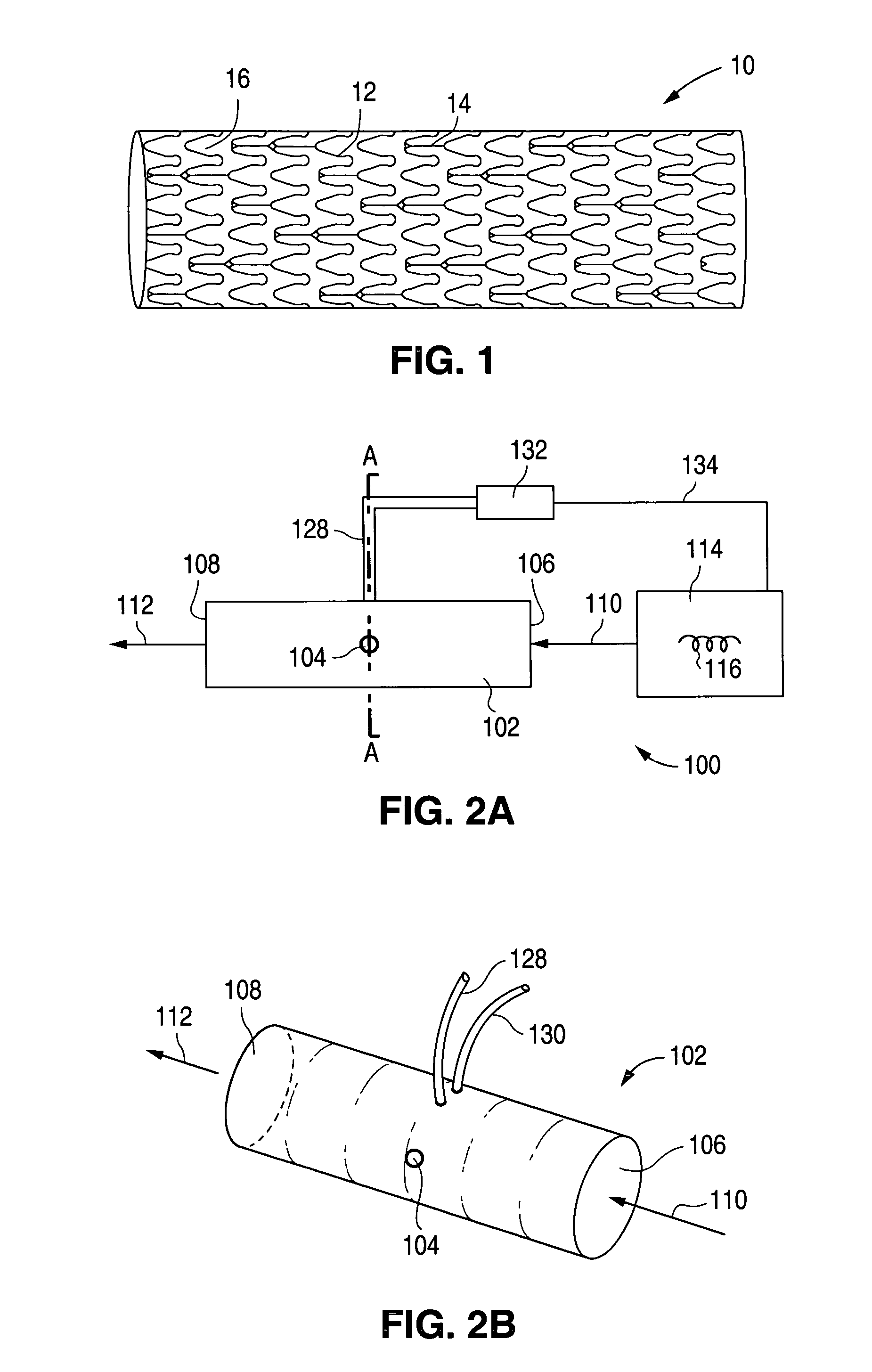
[0080] Embodiments of the present invention relate to coating implantable medical devices such as stents. More generally, embodiments of the present invention may also be used in coating devices including, but not limited to, self-expandable stents, balloon-expandable stents, stent-grafts, vascular grafts, cerebrospinal fluid shunts, pacemaker leads, closure devices for patent foramen ovale, and synthetic heart valves.

[0081] In particular, a stent can have virtually any structural pattern that is compatible with a bodily lumen in which it is implanted. Typically, a stent is composed of a pattern or network of circumferential and longitudinally extending interconnecting structural elements or struts. In general, the struts are arranged in patterns, which are designed to contact the lumen walls of a vessel and to maintain vascular patency. A myriad of strut patterns are known in the art for achieving particular design goals. A few of the more important design characteristics of stent...


PUM

PropertyMeasurementUnit
Lengthaaaaaaaaaa
Fractionaaaaaaaaaa
Fractionaaaaaaaaaa

Abstract

Various embodiments of methods and devices for coating stents are described herein.

Description

BACKGROUND OF THE INVENTION [0001] 1. Field of the Invention [0002] This invention relates to methods and devices for coating stents. [0003] 2. Description of the State of the Art [0004] This invention relates to radially expandable endoprostheses, that are adapted to be implanted in a bodily lumen. An “endoprosthesis” corresponds to an artificial device that is placed inside the body. A “lumen” refers to a cavity of a tubular organ such as a blood vessel. A stent is an example of such an endoprosthesis. Stents are generally cylindrically shaped devices, that function to hold open and sometimes expand a segment of a blood vessel or other anatomical lumen such as urinary tracts and bile ducts. Stents are often used in the treatment of atherosclerotic stenosis in blood vessels. “Stenosis” refers to a narrowing or constriction of a bodily passage or orifice. In such treatments, stents reinforce body vessels and prevent restenosis following angioplasty in the vascular system. “Restenosi...

Claims


Application Information

Patent Timeline
IPC IPC(8): A61L33/00B05D3/02B05D1/02
CPCB05D1/002B05B13/0221B05B13/0228B05B13/0207B05D1/02B05D1/32B05D3/0473A61F2/82
Inventor MCNIVEN, ANDREWHUTER, SCOTTAMICK, JOYCELYNEPPERT, JOSEPHESBECK, THOMASVAN SCIVER, JASON
Owner ABBOTT CARDIOVASCULAR
Why Eureka
Try Eureka