Central station connectivity

a central station and connectivity technology, applied in the field of central station connectivity, can solve the problems of inability to monitor the alarm delivery path, the need for central station operators to retain their pstn services which can be severed, and the slowness of alarm delivery, so as to avoid new equipment and eliminate pstn lines.

Active Publication Date: 2018-10-23
CARRIER CORP
View PDF6 Cites 0 Cited by
  • Summary
  • Abstract
  • Description
  • Claims
  • Application Information

AI Technical Summary

Benefits of technology

[0054]An embodiment of the present invention provides a means for multiplexing messages from a plurality of remote terminals to one or more message receiving terminals as described below in relation to FIG. 6. This arrangement allows the delivery of alarm event messages to central station automation systems using IP-enabled dialer receivers (6.030). This system can provide one or more functional advantages including: prompt alarm delivery, monitoring of the connection to the central station, the avoidance of new equipment at the Central Station and the elimination of PSTN lines.
[0055]According to an embodiment of the invention, alarm event signals generated by burglar and fire alarm panels which are delivered over IP or cellular networks from a customer terminal unit can be converted into a form compatible with third party IP mediation devices thereby allowing the delivery of the alarm event signals into existing third-party IP enabled dialer receiver equipment without the need for individual format conversion devices for each alarm panel.

Problems solved by technology

This method has the disadvantage of requiring the installation of one or more agency terminal units (4.050, 4.052) in every central station (4.000.1, 4.000.2, 4.000.3) which is connected to the IP Network (4.026) used for the alarm delivery network.
While this scheme is universal in nature, it suffers from a number of disadvantages, including: slowness of alarm delivery, inability to monitor the alarm delivery path and the need by the Central Station operators to retain their PSTN services which can be severed.

Method used


Image

  • Central station connectivity
  • Central station connectivity
  • Central station connectivity

Examples


Embodiment Construction

[0091]The invention will be described with reference to the embodiments illustrated in the accompanying drawings.

[0092]FIG. 6 illustrates an embodiment of an alarm transmission network adapted for end-to-end communications to central monitoring stations.

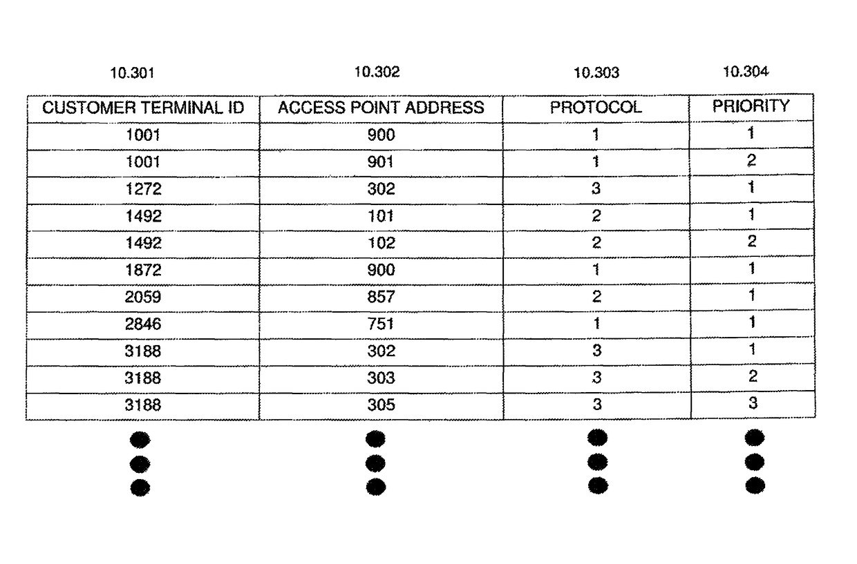
[0093]As shown in FIG. 6, a plurality of customer terminals (6.040, 6.042, 6.044, 6.045) can be selectively connected to one of several central message receiving terminals or central monitoring stations, such as automation systems 6.108, 6.060. A management terminal (6.046) directs the upstream message to an appropriate panel simulator PS (6.070) associated with one of the central station automation system (6.108, 6.060) with which the customer terminal is registered via a selected one of panel simulators (6.070) adapted to decode an upstream message from a customer terminal and regenerate the message in a form compatible with the communication format of a mediation device (6.072) for onward transmission to a selected central station...


PUM


Abstract

Data switching means (6.070, 6.072) for directing messages from a plurality of sources (6.040, 6.042, 6.044, 6,045) and having a common destination (6.108) to a link (6.078) to the common destination, including a first multiplexer (6.070) having a data link (6.074) adapted to receive upstream messages from a plurality of sources, and one or more upstream ports (12.410.1, 12.410.2) each upstream port having a specific port identity, wherein each upstream message includes address information (16.602) identifying the multiplexer and a selected one of the upstream port identities, the transmission means being adapted to link upstream message to the selected upstream port, the selected upstream port being linked to message delivery means (6.072) adapted to address the upstream message to a destination address associated with the message delivery means. Format conversion means can be included to convert the messages from a first format to a second format.

Description

FIELD OF THE INVENTION[0001]This invention relates to improvements in connectivity to central stations used to remotely monitor the activation of communication terminals such as personal emergency response, burglar and fire alarm systems when using new generation communications networks.[0002]The invention will be described in terms of a system which enables the connection of a plurality of public switched telephone network (PSTN) devices via a digital communication network to selected central terminals.[0003]In this specification:[0004]“upstream” in relation to messages refers to the direction from remote device to message receiving centre, and, in relation to devices, refers to the side of the device facing the message receiving centre;[0005]“downstream” in relation to messages refers to the direction from message receiving centre to remote device, and, in relation to devices, refers to the side of the device facing away from the message receiving centre;[0006]“multiplexing” is us...

Claims


Application Information

Patent Timeline
Patent Type & Authority Patents(United States)
IPC IPC(8): H04L12/66H04M11/04H04M7/12H04L12/46
CPCH04M7/122H04M11/04H04M7/128H04L12/4625
Inventor JOHAN, RONBARLOW, JAMESDAHER, GABRIELWU, DANIEL MING ON
Owner CARRIER CORP
Why Eureka
Try Eureka