Acoustic pressure signal channel structure

A technology of channel structure and sound pressure signal, which is used in material analysis, measuring devices, instruments, etc. by optical means, can solve the problems of weak signals and inability to collect, and achieves the goal of reducing interference, facilitating the collection of weak signals, and avoiding effects. Effect

Inactive Publication Date: 2018-11-23
KUNSHAN HEZHI ELECTRICAL EQUIP
View PDF4 Cites 0 Cited by
  • Summary
  • Abstract
  • Description
  • Claims
  • Application Information

AI Technical Summary

Problems solved by technology

[0002] The traditional signal acquisition is to directly install the sensor in the measured gas channel. The heat energy generated by the gas absorbing light energ

Method used


Image

  • Acoustic pressure signal channel structure
  • Acoustic pressure signal channel structure

Examples


Example Embodiment

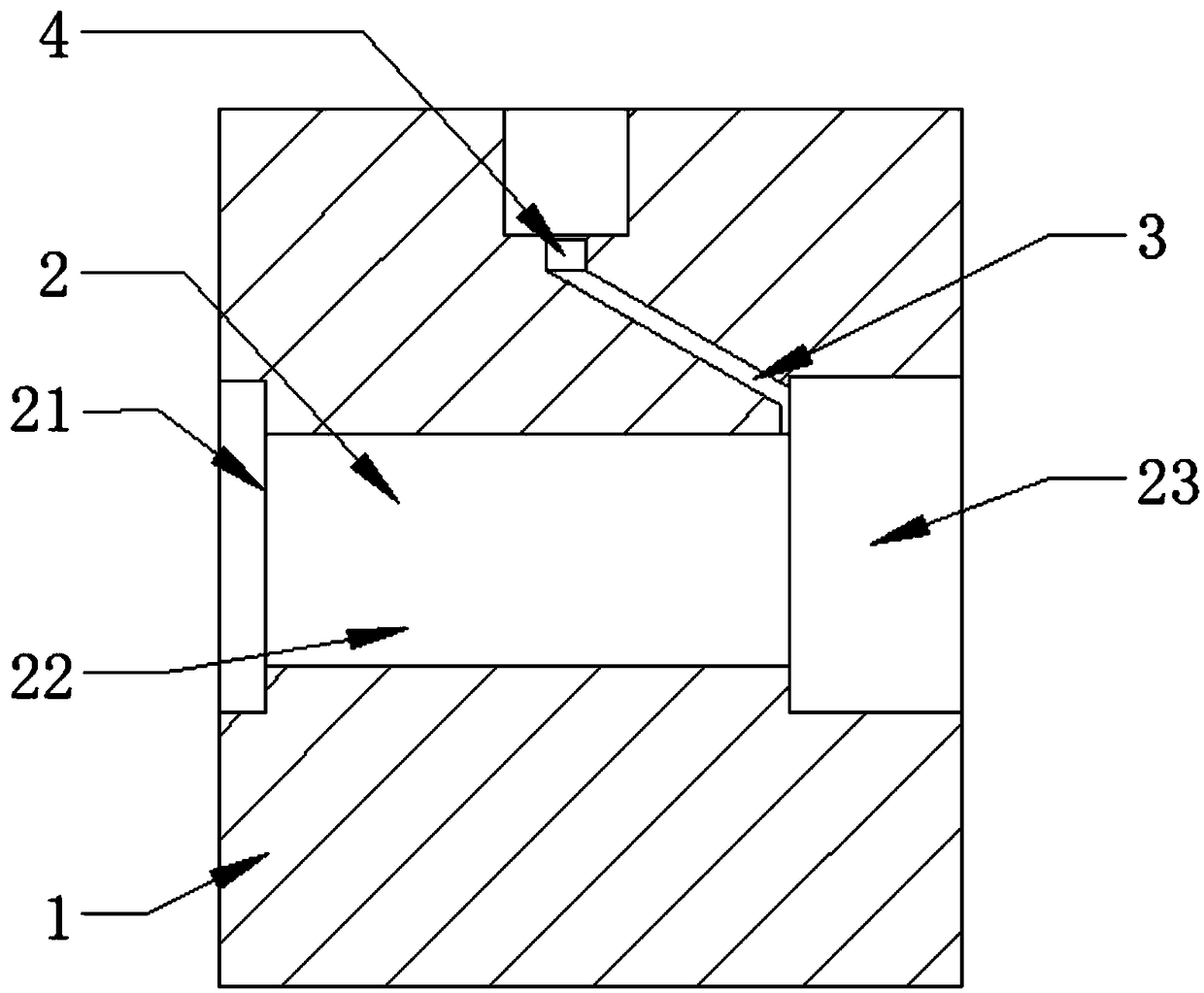
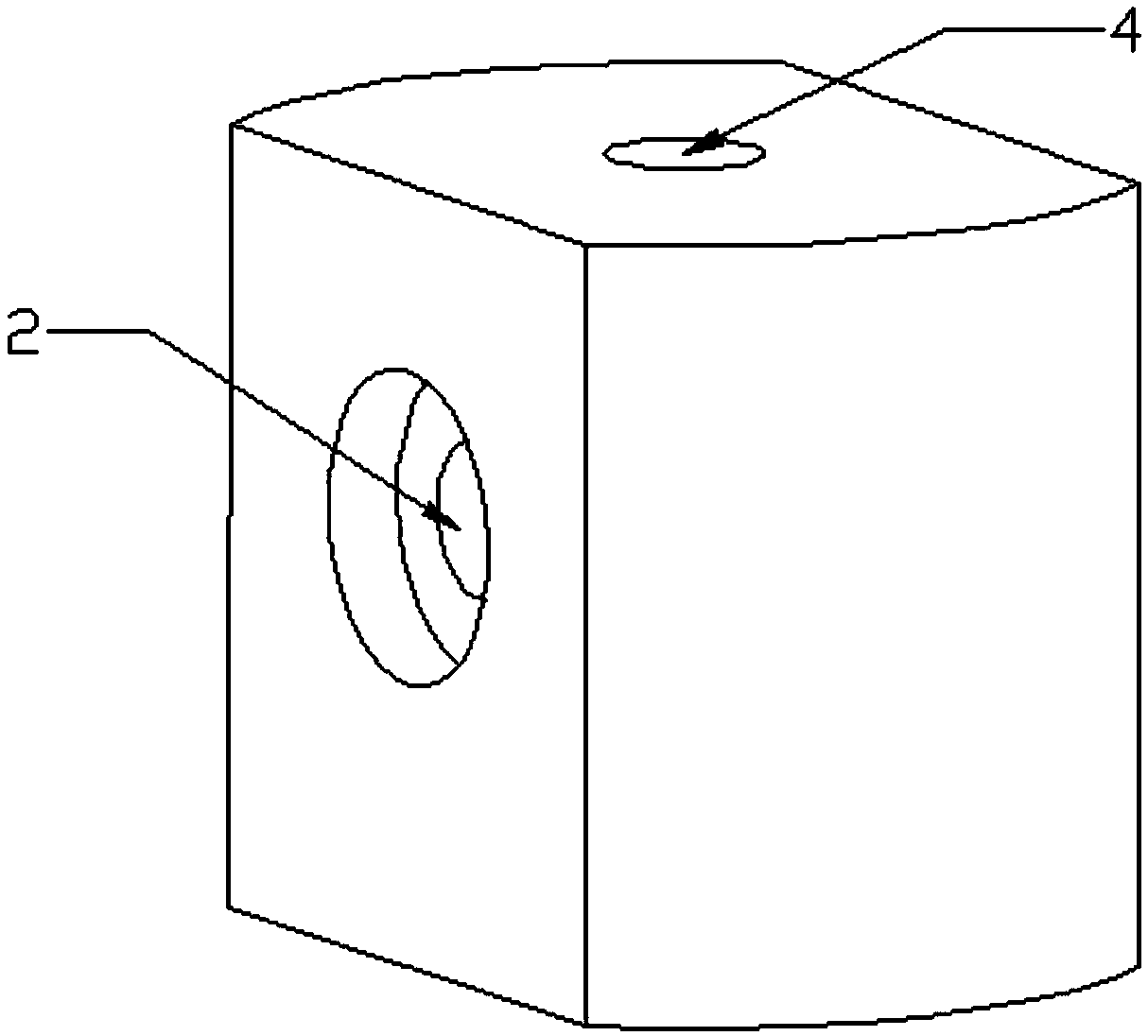
[0014] like figure 1 and figure 2 As shown, a sound pressure signal channel structure includes a channel body 1, a cavity 2 and a microphone 4 are arranged in the channel body 1, an incident window 21 is arranged at one end of the cavity 2, and the other end of the cavity 2 is A collection channel 3 is arranged between the microphones 4 , the cavity 2 includes a sample cell 22 and a conversion cell 23 , the incident window 21 is arranged at one end of the sample cell 22 , and the conversion cell 23 is connected to the sample cell 22 and is arranged at the end of the sample cell 22 . another side. The collection channel 3 is connected to the collection port of the microphone 4 , and the cavity 2 is communicated with the collection port through the collection channel 3 . Further, the collection channel 3 is a microporous channel with a diameter of 1MM, the collection channel ensures sufficient smoothness, and the air pressure is not easily lost in the collection channel 3 . ...


PUM

PropertyMeasurementUnit
Apertureaaaaaaaaaa

Abstract

The invention provides an acoustic pressure signal channel structure. The acoustic pressure signal channel structure comprises a channel body, wherein a cavity and a rheomicrophone are arranged in thechannel body; an incident window piece is arranged on one end of the cavity; a collection channel is arranged between the other end of the cavity and the rheomicrophone; the collection channel is connected with a collection port of the rheomicrophone; the cavity is communicated with the collection port through the collection channel. According to the acoustic pressure signal channel structure provided by the invention, the strength of a collected acoustic pressure signal can be amplified, detection on feeble signals is more sensitive, the rheomicrophone is prevented from being directly mounted in a photoacoustic cell, and interference to a sound field is reduced.

Description

technical field [0001] The invention belongs to the technical field of micro sound detection, and in particular relates to a sound pressure signal channel structure. Background technique [0002] The traditional signal acquisition is to install the sensor directly in the gas channel to be measured. The heat energy generated after the gas absorbs the light energy is converted into sound pressure and directly acts on the microphone. When measuring a certain low-concentration gas, the signal is weak and cannot be collected. SUMMARY OF THE INVENTION [0003] The purpose of the present invention is to provide a sound pressure signal channel structure, which amplifies the collected sound pressure signal strength, prevents the microphone from being directly installed in the photoacoustic pool, and reduces the interference to the sound field. [0004] The invention provides the following technical solutions: [0005] A sound pressure signal channel structure includes a channel bo...

Claims


Application Information

Patent Timeline
IPC IPC(8): G01N21/17
CPCG01N21/1702G01N2021/1704
Inventor 包迎兵佘裕岳宋明才
Owner KUNSHAN HEZHI ELECTRICAL EQUIP
Why Eureka
Try Eureka