Compressive heat-resistant tube structure for RV

a technology of compression heat resistance and tube structure, which is applied in the direction of mechanical equipment, other domestic articles, synthetic resin layered products, etc., can solve the problems of increased inability to provide a simple way for users, and inconvenient piping, so as to reduce the required parts and labor costs, and identify easily and quickly

Active Publication Date: 2018-11-13
CHIANG SHEN EN
View PDF11 Cites 3 Cited by
  • Summary
  • Abstract
  • Description
  • Claims
  • Application Information

AI Technical Summary

Benefits of technology

[0003]The primary objective of the present invention is to provide a compressive heat-resistant tube structure for RV. The compressive heat-resistant tube structure for RV comprises a compressive heat-resistant multi-layer tube. The compressive heat-resistant multi-layer tube comprises a compressive heat-resistant PVC soft inner tube, a polyester dense crocheted covering layer, and a compressive PVC soft outer tube. An outer surface of the compressive PVC soft outer tube is provided with an identification surface layer portion. The identification surface layer portion is disposed on the compressive PVC soft outer tube in a circumferential or semi-circumferential manner. The identification surface layer portion may be blue, red or black, or may be marked with characters or signs. The compressive heat-resistant PVC soft inner tube is wrapped by the polyester dense crocheted covering layer. The polyester dense crocheted covering layer is wrapped by the compressive PVC soft outer tube. Through the cooperation of the compressive heat-resistant PVC soft inner tube, the polyester dense crocheted covering layer and the compressive PVC soft outer tube, the pressure resistance of the compressive heat-resistant multi-layer tube can be improved to 300 PSI. The outer surface of the compressive PVC soft outer tube is provided with the identification surface layer portion for distinguishing a cold water tube, a hot water tube or a waste water tube, enabling the user to easily and quickly identify each tube for connection of the tubes. The soft compressive heat-resistant multi-layer tube can be bent according to the demand of use, not limited to the arrangement of the edge wiring so as to reduce the required parts and the labor cost. The soft compressive heat-resistant multi-layer tube is convenient for use and can be installed conveniently.

Problems solved by technology

This way is inconvenient for piping, and the required parts and the labor cost are increased.
The pipe structure is unable to provide a simply way for the user to identify the purpose of each pipe.
It is easy to make a mistake in the connection of the pipes.

Method used


Image

  • Compressive heat-resistant tube structure for RV
  • Compressive heat-resistant tube structure for RV
  • Compressive heat-resistant tube structure for RV

Examples


Embodiment Construction

[0013]Advantages and features of the inventive concept and methods of accomplishing the same may be understood more readily by reference to the following detailed description of embodiments and the accompanying drawings. The inventive concept may, however, be embodied in many different forms and should not be construed as being limited to the embodiments set forth herein.

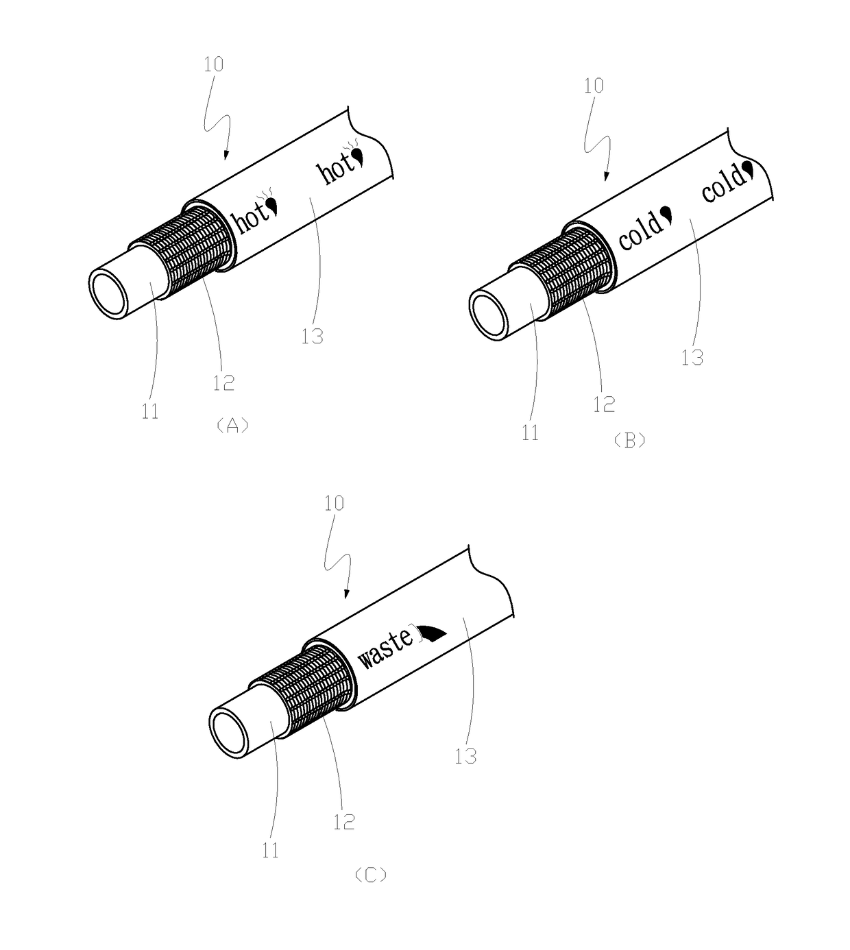
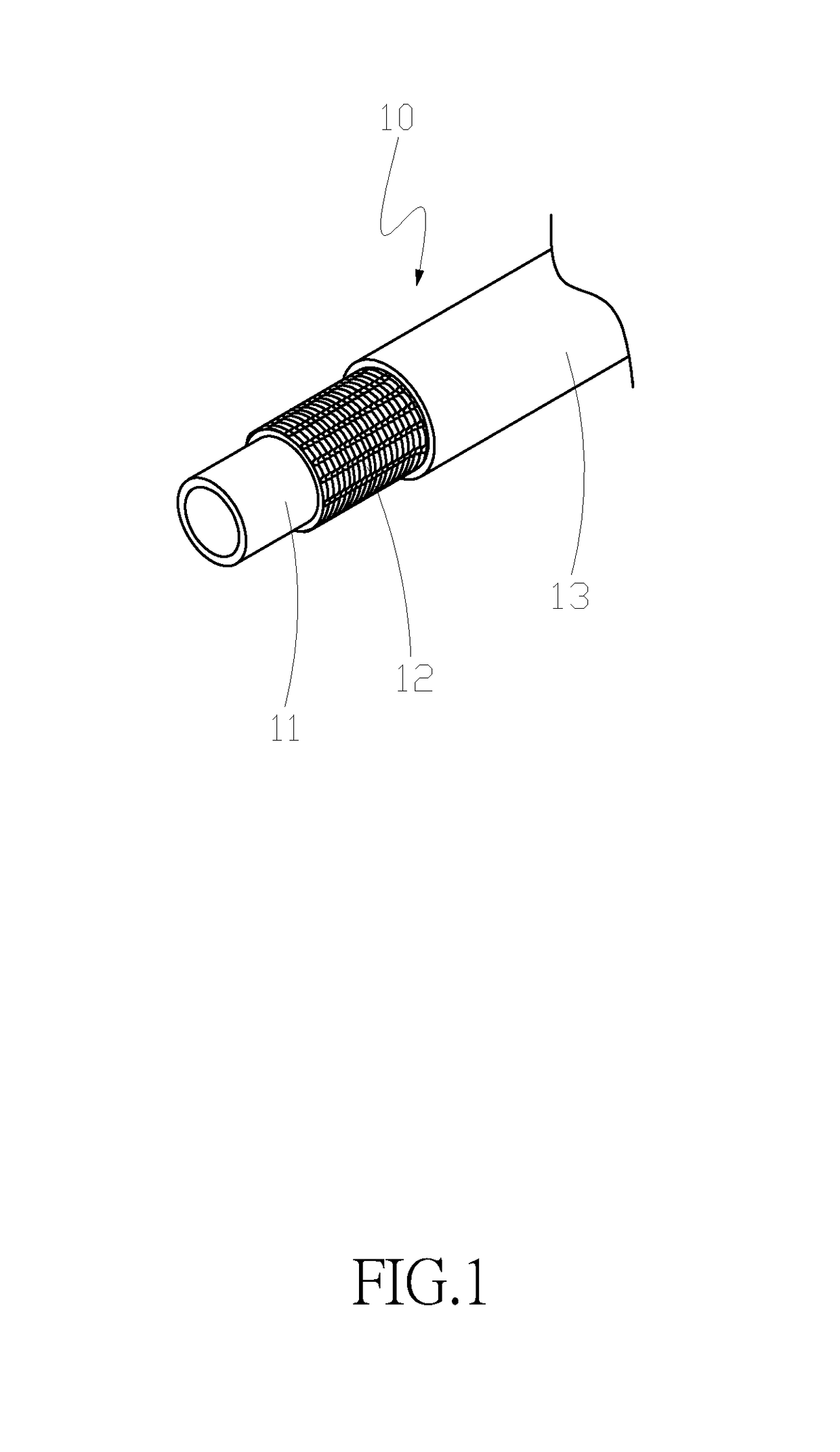
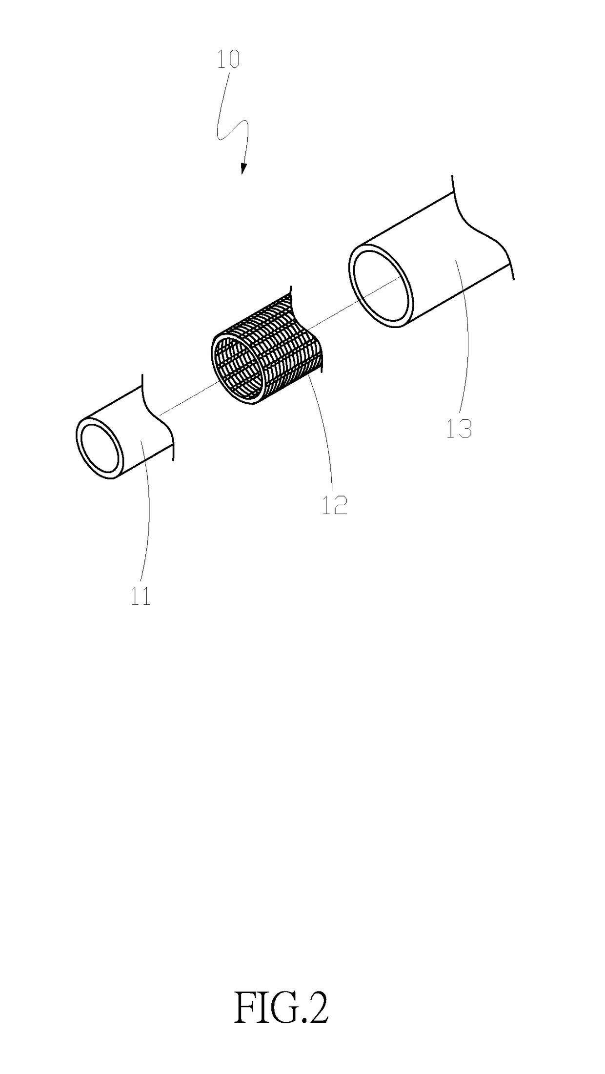
[0014]Referring to FIG. 1 through FIG. 3, FIG. 1 is a perspective view of the compressive heat-resistant tube structure for RV of the present invention. FIG. 2 is an exploded view of the compressive heat-resistant tube structure for RV of the present invention. FIG. 3 is a side sectional view of the compressive heat-resistant tube structure for RV of the present invention.

[0015]The compressive heat-resistant tube structure for RV of the present invention comprises a compressive heat-resistant multi-layer tube 10. The compressive heat-resistant multi-layer tube 10 comprises a compressive heat-resistant PVC soft inner...


PUM

PropertyMeasurementUnit
compressiveaaaaaaaaaa
compressive heat-resistantaaaaaaaaaa
flexibleaaaaaaaaaa

Abstract

A compressive heat-resistant tube structure for RV includes a compressive heat-resistant multi-layer tube. The compressive heat-resistant multi-layer tube includes a compressive heat-resistant PVC soft inner tube, a polyester dense crocheted covering layer, and a compressive PVC soft outer tube. An outer surface of the compressive PVC soft outer tube is provided with an identification surface layer portion. The identification surface layer portion enables the user to easily and quickly identify each tube for connection of tubes. The soft compressive heat-resistant multi-layer tube can be bent according to the demand of use, not limited to the arrangement of the edge wiring. The soft compressive heat-resistant multi-layer tube is convenient for use and can be installed conveniently.

Description

FIELD OF THE INVENTION[0001]The present invention relates to a compressive heat-resistant tube structure for RV, and more particularly to a tube structure applied to a camping car.BACKGROUND OF THE INVENTION[0002]FIG. 9 shows a conventional water pipe structure for RV. A pipe assembly installed inside a camping car comprises a plurality of hard pipes 21 in cooperation with T-shaped branching connectors 22, a plurality of retaining rings 23, a plurality of control valve heads 24, and a plurality of corner connectors 25. The hard pipes 21 are cut for a required length according to the corner of the installation space and then fixedly connected with the T-shaped branching connectors 22 and the retaining rings 23. The ends of the hard pipes 22 are connected with the control valve heads 24 through the retaining rings 23, respectively. The piping arrangement of the hard pipes 21 must be fitted with the RV body structure in the form of an edge wiring. At the corners, it is necessary to use...

Claims


Application Information

Patent Timeline
Patent Type & Authority Patents(United States)
IPC IPC(8): F16L55/00F16L11/10F16L11/12
CPCF16L11/125F16L11/124F16L11/10B32B1/08B32B5/028B32B27/12B32B27/304B32B2250/03B32B2262/0276B32B2307/306B32B2307/402B32B2307/546B32B2597/00B32B2605/08F16L11/085B32B1/00
Inventor CHIANG, SHEN-EN
Owner CHIANG SHEN EN
Why Eureka
Try Eureka