Vehicle safety device using visible light communication

a safety device and vehicle technology, applied in the direction of pedestrian/occupant safety arrangement, vehicle sub-unit features, instruments, etc., can solve the problems of inability to provide concrete and practical means, drawbacks of existing radio frequency communication, accidents concerning the operation of vehicles, etc., to reduce the risk of collision, reduce the risk of fuel waste, and reduce the effect of collision risk

Inactive Publication Date: 2018-11-20
YUYANG D&U CO LTD
View PDF17 Cites 3 Cited by
  • Summary
  • Abstract
  • Description
  • Claims
  • Application Information

AI Technical Summary

Benefits of technology

[0022]As described above, according to the present disclosure, when the driver of the main vehicle operates the accelerator pedal while any one of the following vehicles is operating its brake pedal, the driver receives an alarm signal, so as to reduce the risk of collision with the preceding vehicle as well as the waste of fuel due to unnecessary acceleration.
[0023]In addition, when the driver of the main vehicle operates the accelerator pedal while any one of the following vehicles is operating its accelerator pedal, the driver receives an alarm signal, so as to reduce the risk of collision with the preceding vehicle and inform the driver of the timing for operating the brake pedal.
[0024]In addition, when making a lane change or direction change, the driver is provided with an alarm signal according to the distance to the following vehicle for enabling the driver to safely change the lane or steer as desired.
[0025]In addition, intuitive information is displayed for a driver on a display unit about whether the drivers of the preceding vehicles are placing their feet on the brake pedals, operating the brake pedals, or depressing the brake pedals to the fullest. This informs the driver of the timing for operating the accelerator pedal especially on the congested road, reduces the risk of collision with the preceding vehicles, and tells the driver, when making a lane change or steering, the distance to the following vehicle.
[0026]Unlike the conventional vehicle safety device which has reported to the main vehicle by inter-vehicle communication only with changing speeds of the preceding vehicle, the present disclosure in some embodiments provides the driver with an early information of when the preceding vehicle's driver places the foot on the brake pedal before the speed of the preceding vehicle is decelerated, and thereby enables the driver to instantaneously detect traffic changes due to traffic situations further ahead, which is greatly useful for safe driving.
[0027]In addition, a vehicle safety device using visible light communication according to some embodiment of the present disclosure needs no separate external network, requiring low device complexity toward a high distribution rate. Then, the driver can easily grasp the state of the road traffic to take immediate action without using a collision algorithm.

Problems solved by technology

Vehicle can provide comfort for human beings, but accidents concerning the operation of vehicles are still a problem to be solved.
In addition, no crosstalk thanks to the straightness of the light precludes the issue of radio wave crosstalk caused by multiple vehicles, which is a drawback of existing radio frequency communication.
Patents have been disclosed recently concerning the safety of vehicles using such visible light communication, but there is no provision of a concrete and practical means which can be widely spread by applying visible light communication.
This leaves the driver of the following vehicle ignorant of any possible emergency situation lying ahead.
Therefore, when an incident occurs ahead, the following vehicle operators looking only at the brake taillight of the lead vehicle risk a chain collision due to a sudden stop of the lead vehicle.
Besides such an extreme situation, with brake taillights designed to be lit upon operating the brake pedal, the driver is uninformed of details, such as whether the lead vehicle operator gently put the foot on the brake pedal.
This would mislead a driver to accelerate watching only that the lead vehicles' brake taillights are not lit until the driver suddenly returns to the brake pedal operation subsequent to the lead vehicles' brake pedal operation, which leads to road safety issues.
In addition, on the side of the preceding vehicle, a suspected, but unidentifiable accelerator pedal operation of its following vehicle hinders the preceding vehicle from braking in a quick timely manner due to a concern for a rear-ending accident by that following vehicle.

Method used


Image

  • Vehicle safety device using visible light communication
  • Vehicle safety device using visible light communication
  • Vehicle safety device using visible light communication

Examples


first embodiment

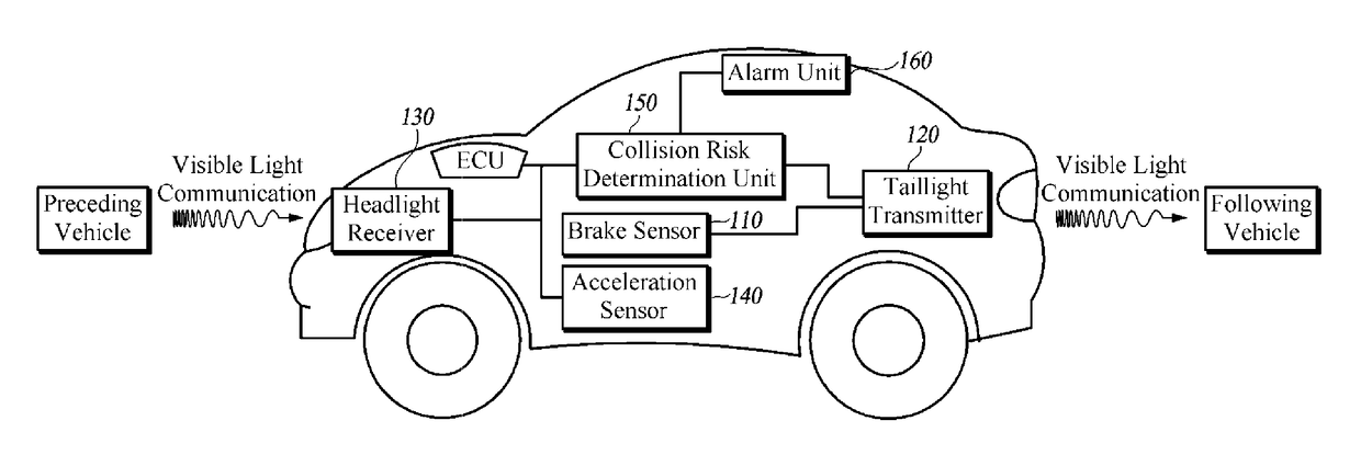
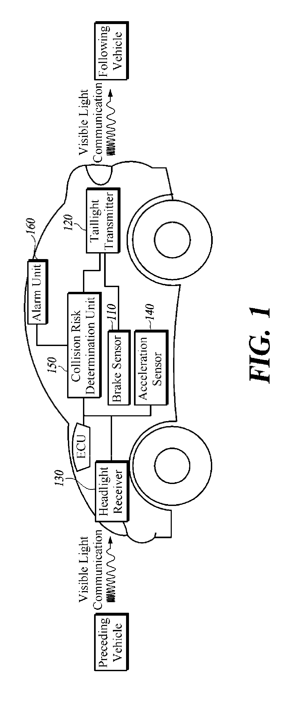
[0033]FIG. 1 is a schematic block diagram of a vehicle safety apparatus using visible light communication according to the present disclosure.

[0034]Referring to FIG. 1, the vehicle safety apparatus using visible light communication according to the first embodiment includes a brake sensor 110, a taillight transmitter 120, a headlight receiver 130, an acceleration sensor 140, a collision risk determination unit 150 and an alarm unit 160.

[0035]The brake sensor 110 is installed on a braking system of the vehicle, for example, a brake pedal, which is installed with the vehicle safety apparatus using visible light communication according to this embodiment.

[0036]The brake sensor 110 distinguishes and detects when the driver operates the brake pedal with a weak strength from when the brake pedal is strongly operated. Therefore, the brake sensor 110 detects an event of operating the brake pedal by the driver below a preset strength to generate a weak deceleration signal, and detects anothe...

second embodiment

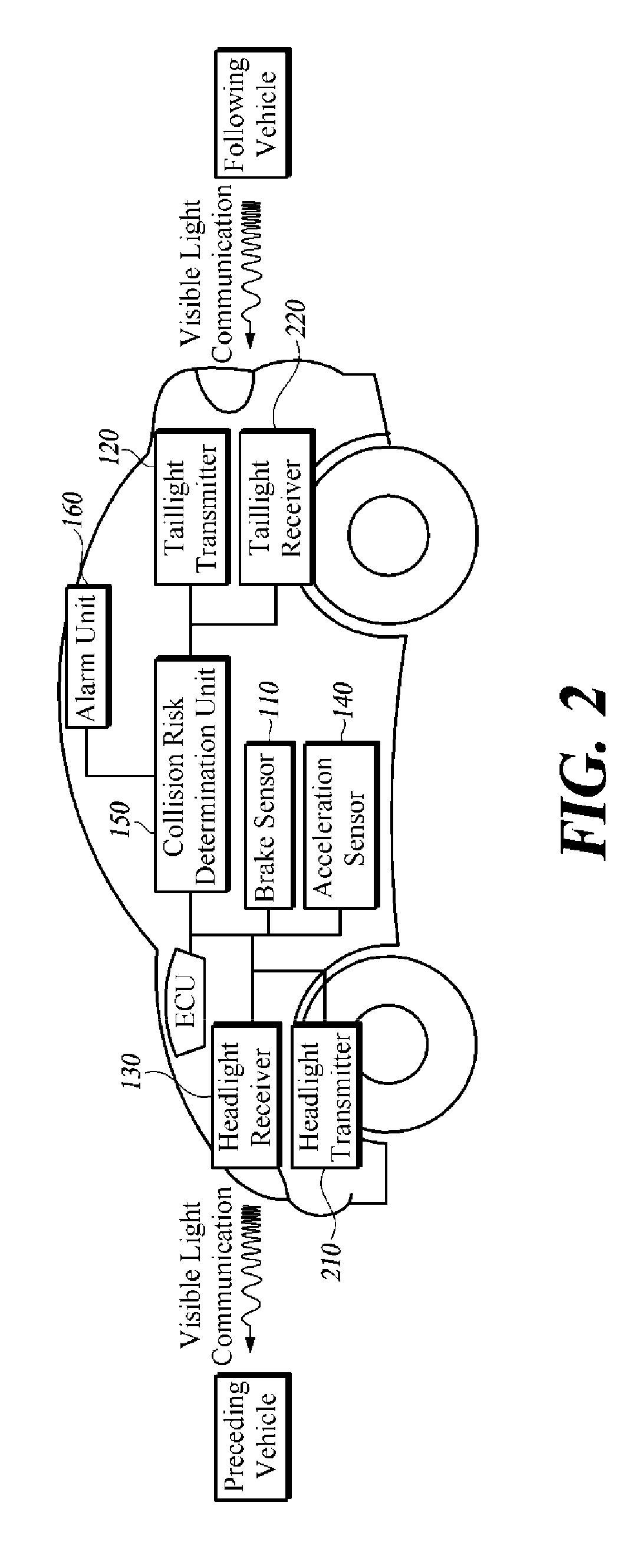
[0057]FIG. 2 is a schematic block diagram of a vehicle safety apparatus using visible light communication according to the present disclosure.

[0058]Referring to FIG. 2, the vehicle safety apparatus using visible light communication according to the second embodiment includes a headlight receiver 130, a headlight transmitter 210, a taillight transmitter 120, a taillight receiver 220, a brake sensor 110, an acceleration sensor 140, a collision risk determination unit 150 and an alarm unit 160.

[0059]The vehicle safety apparatus using visible light communication according to the second embodiment is equivalent to the first embodiment with additional components of the headlight transmitter 210 and the taillight receiver 220.

[0060]The headlight receiver 130, the taillight transmitter 120 and the brake sensor 110 shown in FIG. 2 are the same as those in FIG. 1. Therefore, only the difference of the acceleration sensor 140, the headlight transmitter 210, the taillight receiver 220, the coll...

third embodiment

[0077]FIG. 3 is a schematic block diagram of a vehicle safety apparatus using visible light communication according to the present disclosure.

[0078]Referring to FIG. 3, a vehicle safety device using visible light communication according to a third embodiment of the present disclosure includes a headlight receiver 130, a headlight transmitter 210, a taillight transmitter 120, a taillight receiver 220, a brake sensor 110, an acceleration sensor 140, a turn signal sensor 310, a collision risk determination unit 150, a distance measurement unit 320 and an alarm unit 160.

[0079]The vehicle safety apparatus using visible light communication according to the third embodiment is equivalent to the second embodiment with additional components of the turn signal sensor 310 and the distance measurement unit 320.

[0080]The headlight receiver 130, the headlight transmitter 210, the taillight transmitter 120, the taillight receiver 220 and the brake sensor 110 shown in FIG. 3 are the same as those i...


PUM


Abstract

A vehicle safety device using visible light communication is disclosed. A vehicle safety apparatus using visible light communication includes a brake sensor on a main vehicle brake pedal for generating a deceleration signal by a degree of braking, an acceleration sensor on a main vehicle accelerator pedal for generating an acceleration signal by a degree of acceleration, a visible light receiver for receiving a preceding-vehicle signal from at least one preceding vehicle and a following-vehicle signal from at least one following vehicle, a visible light transmitter for transmitting a main vehicle signal to the preceding vehicle and vehicles, a collision risk determination unit for determining whether a danger of collision is present based on the preceding-vehicle signal, the following and main-vehicle signal, and an alarm unit for issuing an alarm to driver in response to the collision risk determination unit determining the presence of a danger of collision.

Description

CROSS-REFERENCE TO RELATED APPLICATION[0001]This application is a U.S. National Phase Application under 35 U.S.C. 371 of International Application No. PCT / KR2015 / 007445 filed on Jul. 17, 2015 and published in Korean as WO 2016 / 133251 A1 on Aug. 25, 2016. This application claims priority under 35 U.S.C § 119(a) of Patent Application No. 10-2015-0023582, filed on Feb. 16, 2015 in Korea. The entire contents of the above applications are incorporated herein by reference. In addition, this non-provisional application claims priority in countries, other than the U.S., with the same reason based on the Korean patent application, the entire content of which is hereby incorporated by reference.TECHNICAL FIELD[0002]The present disclosure in some embodiments relates to a vehicle safety device using visible light communication.BACKGROUND[0003]The statements in this section merely provide background information related to the present disclosure and do not necessarily constitute prior art.[0004]V...

Claims


Application Information

Patent Timeline
Patent Type & Authority Patents(United States)
IPC IPC(8): B60W50/14B60Q5/00B60R21/013B60W30/08B60Q1/52B60W30/095G08G1/16
CPCB60W50/14B60Q1/525B60Q5/00B60R21/013B60W30/08G08G1/161G08G1/166G08G1/167B60W30/0956B60W2550/308B60W2050/146G08G1/096791G08G1/163B60Q1/0017B60Q9/008B60Q5/006B60Y2300/08B60Y2400/304B60W2554/801
Inventor KIM, SANGOKKIM, BYUNGOHKIM, DONGSIKYOON, SANG-HO
Owner YUYANG D&U CO LTD
Why Eureka
Try Eureka