Optical sectioning apparatus using advanced optical interference microscopy

a technology of optical interference and optical sectioning, which is applied in the field of optical sectioning apparatus, can solve the problems of affecting the image quality of the frozen section, the inability of the pathologist to guarantee the clean removal of the tumor, and the damage to the tissue structure, so as to improve the relative strength of the fluorescent signal, shorten the exposure time, and speed up the effect of taking images

Active Publication Date: 2018-12-11
ACUSOLUTIONS INC
View PDF11 Cites 3 Cited by
  • Summary
  • Abstract
  • Description
  • Claims
  • Application Information

AI Technical Summary

Benefits of technology

[0008]One objective of the present invention is to disclose an optical sectioning apparatus, in which a first dichroic splitter is disposed between a beam splitter and a first objective lens to block a short-wavelength light beam and thereby increase a relative strength of a fluorescent signal, shorten an exposure time, and speed up taking images.
[0009]Another objective of the present invention is to disclose an optical sectioning apparatus, in which a first dichroic splitter will filter out a short-wavelength light beam so that when a fluorescent light beam emitted from a sample passes through the first dichroic splitter, the fluorescent light beam will have a good relative strength to shorten an exposure time and speed up taking images.
[0010]Still another objective of the present invention is to disclose an optical sectioning apparatus, in which a sensor unit has a long-wavelength-pass filter to further filter out a short-wavelength light beam to increase the relative strength of a fluorescent signal, and thereby shorten an exposure time and speed up taking images.
[0016]a first dichroic splitter, having a first side, a second side, and a third side, with the first side facing the short wavelength light source apparatus, the third side facing the second side of the beam splitter, and being capable of providing a light-blocking effect on a band of wavelengths shorter than a preset wavelength, and the short wavelength light beam having a wavelength shorter than the preset wavelength;
[0027]In one embodiment, a first polarizer is disposed between the wide band light source apparatus and the beam splitter, a second polarizer is disposed in front of the two-dimensional monochrome sensing device, a first quarter-wave plate is disposed between the first objective lens and the first dichroic splitter, and a second quarter-wave plate is disposed between the optical path delay unit and the second objective lens, wherein the first polarizer has a first polarization direction, the second polarizer has a second polarization direction orthogonal to the first polarization direction, the first quarter-wave plate has a first optical axis direction, the second quarter-wave plate has a second optical axis direction, and both the first optical axis direction and the second optical axis direction are disposed within a range formed by the first polarization direction and the second polarization direction to enhance an interference effect and promote an imaging quality.

Problems solved by technology

In conventional tumor surgery, it takes a lot of time for a pathologist to examine a frozen section to determine if a tumor is cleanly removed.
As a result, when the time allowed for the surgery is shorter than the time needed for the pathologist to complete the assessment of intraoperative pathological margin, the tumor cannot be guaranteed to be cleanly removed.
During the process of preparing a frozen section of a sample, if the sample contains much water, a formed crystal ice structure will cause a damage to the tissue structure of the sample; and if the sample contains much fat, the fat will still be not frozen at temperatures around −20° C. where the other tissues are already frozen, and is therefore easy to slip off from the frozen section to cause an artifact to the frozen section.
Due to these two disadvantages, a fluorescent signal out of a sample will very weak.

Method used


Image

  • Optical sectioning apparatus using advanced optical interference microscopy
  • Optical sectioning apparatus using advanced optical interference microscopy
  • Optical sectioning apparatus using advanced optical interference microscopy

Examples


Embodiment Construction

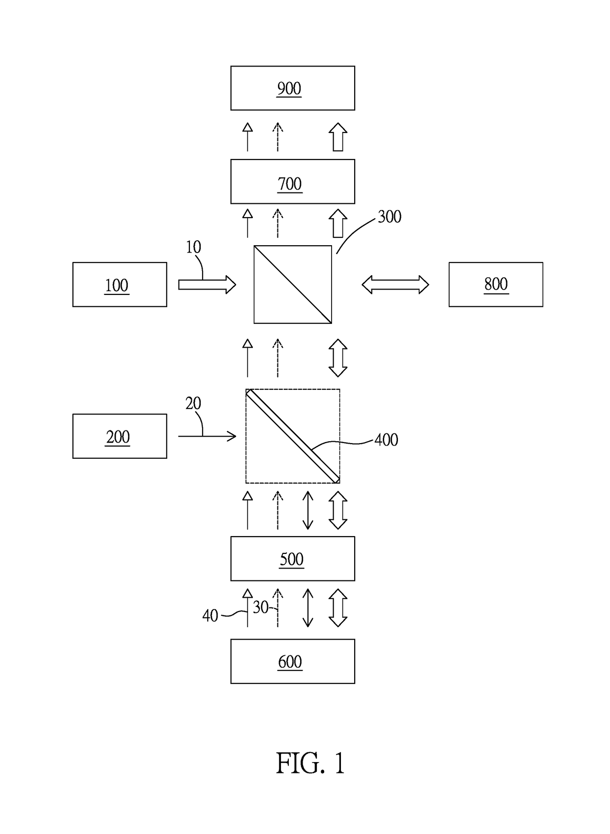
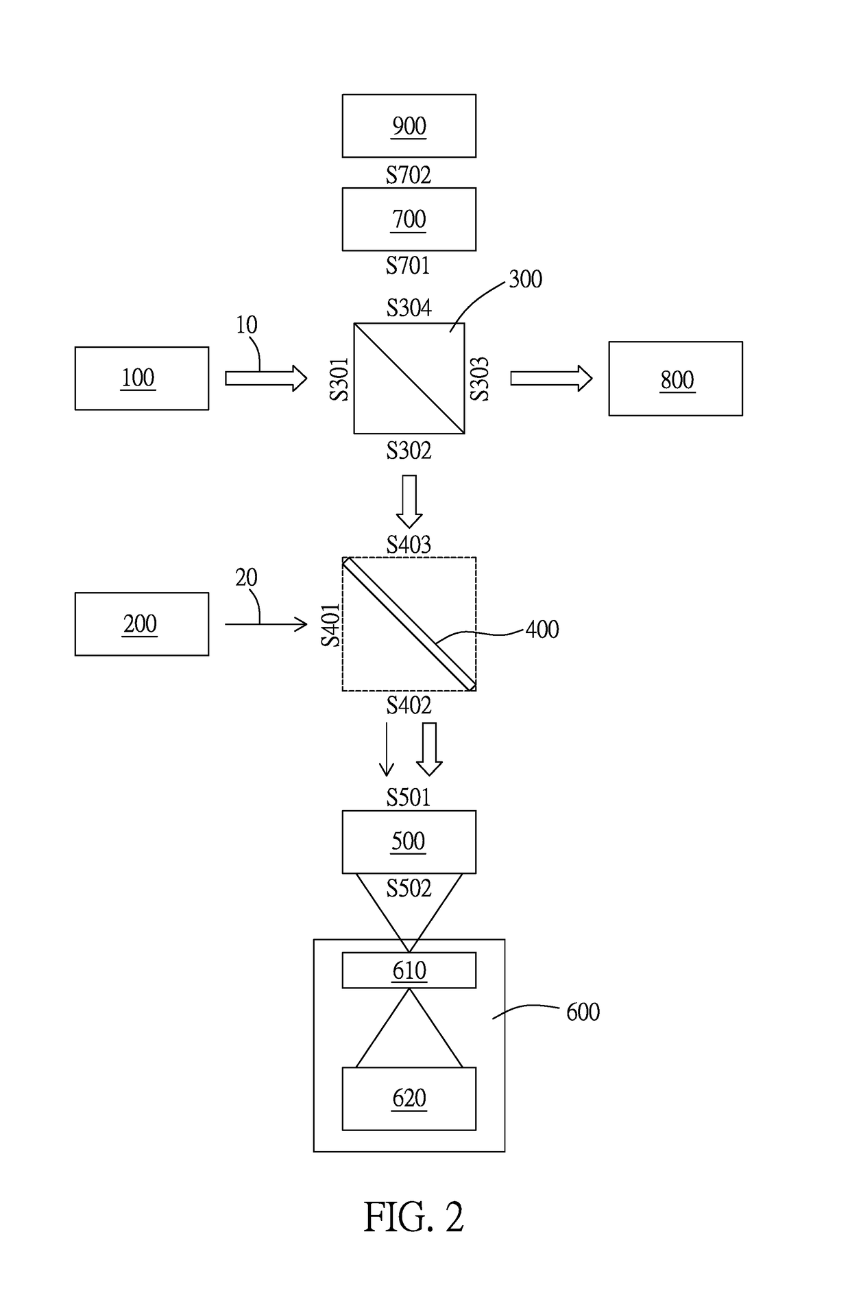
[0041]Please refer to FIG. 1-2, in which, FIG. 1 illustrates a block diagram of an optical sectioning apparatus using optical interference microscopy and fluorescence microscopy according to one embodiment of the present invention, and FIG. 2 illustrates a beam splitting operation and a focusing operation of the optical sectioning apparatus in FIG. 1.

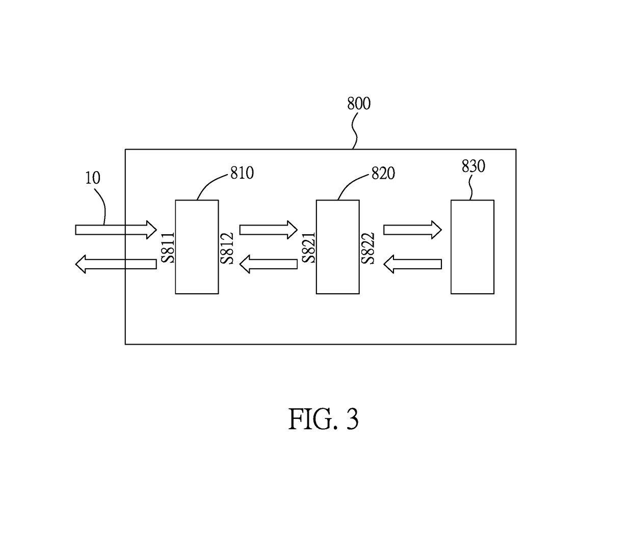
[0042]As illustrated in the figures, the optical sectioning apparatus using optical interference microscopy and fluorescence microscopy includes: a wide band light source apparatus 100, a short wavelength light source apparatus 200, a beam splitter 300, a first dichroic splitter 400, a first objective lens 500, a sample carrier unit 600, a projection lens 700, a reference arm unit 800, and a sensor unit 900.

[0043]The wide band light source apparatus 100 is used to generate a wide band light beam 10 (indicated by a hollow arrow); the short wavelength light source apparatus 200 is used to generate a short wavelength light beam 20 (indicat...


PUM


Abstract

An optical sectioning apparatus using optical interference microscopy and fluorescence microscopy, including: a beam splitter capable of splitting an incident light beam into a reflected light beam and a transmitted light beam; a wide band light source for providing the incident light beam; a reference arm unit for making the transmitted light beam travel a round trip along an adjustable optical path; a short wavelength light source; a first dichroic splitter, with a first side facing the short wavelength light source and a third side facing the beam splitter, being capable of providing a light-blocking effect on wavelengths shorter than a preset wavelength; an objective lens, with a collimated side facing a second side of the first dichroic splitter; a sample carrier unit facing a focal side of the objective lens; and a projection lens and a sensor units for receiving an output light beam.

Description

BACKGROUND OF THE INVENTIONField of the Invention[0001]The present invention relates to an optical sectioning apparatus, especially to an optical sectioning apparatus using optical interference microscopy and fluorescence microscopy.Description of the Related Art[0002]In conventional tumor surgery, it takes a lot of time for a pathologist to examine a frozen section to determine if a tumor is cleanly removed. As a result, when the time allowed for the surgery is shorter than the time needed for the pathologist to complete the assessment of intraoperative pathological margin, the tumor cannot be guaranteed to be cleanly removed.[0003]During the process of preparing a frozen section of a sample, if the sample contains much water, a formed crystal ice structure will cause a damage to the tissue structure of the sample; and if the sample contains much fat, the fat will still be not frozen at temperatures around −20° C. where the other tissues are already frozen, and is therefore easy to...

Claims


Application Information

Patent Timeline
Patent Type & Authority Patents(United States)
IPC IPC(8): G01B9/02A61B5/00H04N7/18G02B21/00
CPCG01B9/0203A61B5/0066G01B9/02041G01B9/02057G01B9/02091G02B21/0056G02B21/0076H04N7/18G01B9/02065G01B2290/60G02B21/14G02B21/16G02B21/367G01B2290/70
Inventor TSAI, CHIEN-CHUNGHSU, KUANG-YU
Owner ACUSOLUTIONS INC
Why Eureka
Try Eureka