Aromatic heterocyclic derivative, material for organic electroluminescent element, and organic electroluminescent element

a heterocyclic derivative and organic technology, applied in the direction of organic chemistry, luminescent compositions, organic semiconductor devices, etc., can solve the problem that the efficiency of fluorescent organic el devices needs to be improved, and achieve the effect of reducing the drive voltage and high efficiency

Active Publication Date: 2019-02-05
IDEMITSU KOSAN CO LTD
View PDF76 Cites 1 Cited by
  • Summary
  • Abstract
  • Description
  • Claims
  • Application Information

AI Technical Summary

Benefits of technology

[0076]According to the embodiment(s), an organic EL device that emits at a high efficiency and is driven at a lower drive voltage, an aromatic hete...

Problems solved by technology

However, as compared with a phosphorescent organic EL device, a ...

Method used


Image

  • Aromatic heterocyclic derivative, material for organic electroluminescent element, and organic electroluminescent element
  • Aromatic heterocyclic derivative, material for organic electroluminescent element, and organic electroluminescent element
  • Aromatic heterocyclic derivative, material for organic electroluminescent element, and organic electroluminescent element

Examples


first exemplary embodiment

[0211]This exemplary embodiment utilizes TTF phenomenon. The TTF phenomenon will be initially described below.

[0212]Holes and electrons respectively injected from an anode and a cathode are recombined in an emitting layer to generate excitons. As for the spin state, as is conventionally known, singlet excitons account for 25% and triplet excitons account for 75%. In a conventionally known fluorescent device, light is emitted when singlet excitons of 25% are relaxed to the ground state. The remaining triplet excitons of 75% are returned to the ground state without emitting light through a thermal deactivation process. Accordingly, the theoretical limit value of the internal quantum efficiency of a conventional fluorescent device is believed to be 25%.

[0213]The behavior of triplet excitons generated within an organic substance has been theoretically examined. According to S. M. Bachilo et al. (J. Phys. Chem. A, 104, 7711 (2000)), assuming that high-order excitons such as quintet excit...

second exemplary embodiment

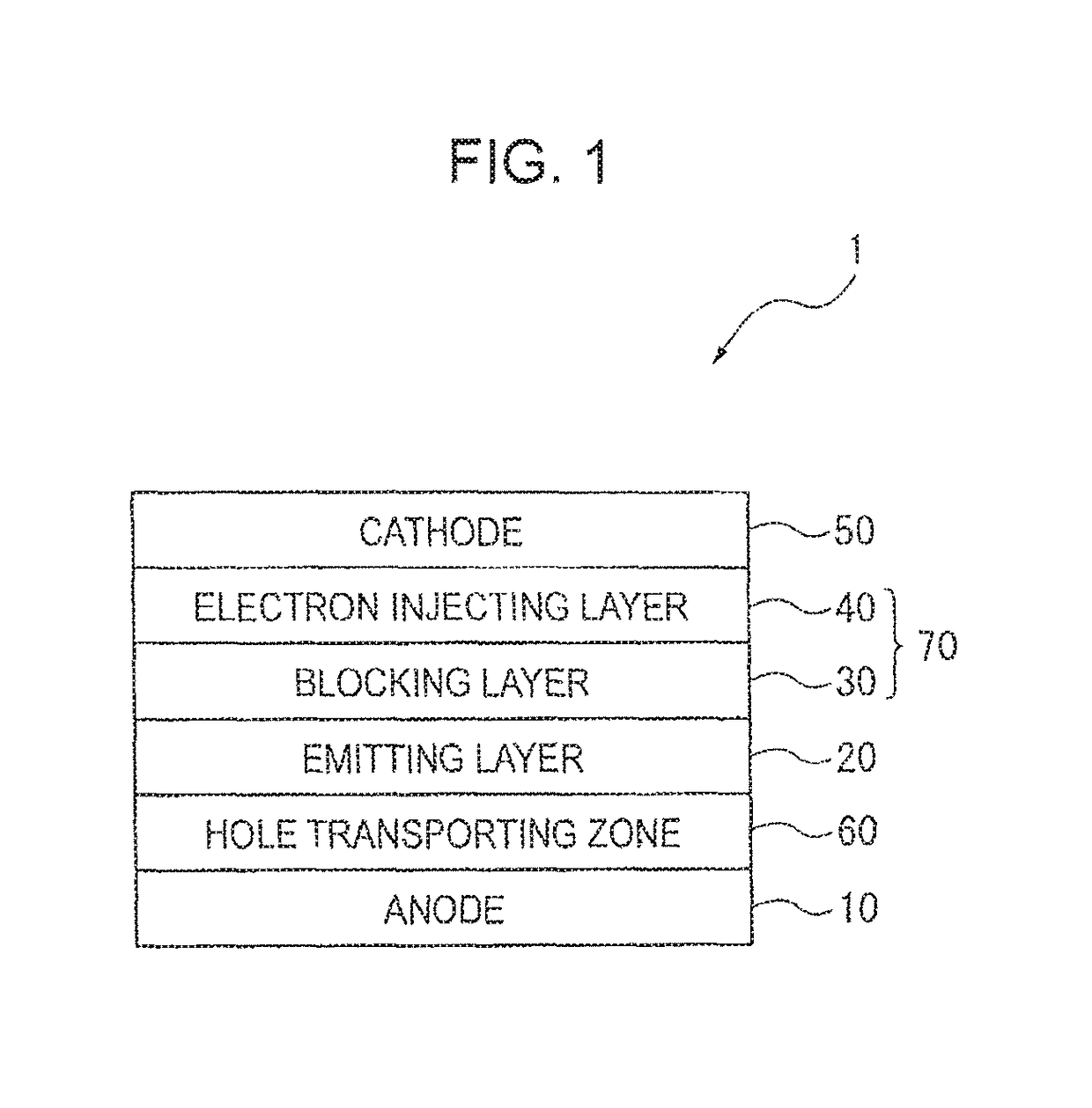
[0432]FIG. 8 shows one example of an organic EL device 2 according to a second exemplary embodiment.

[0433]The organic EL device according to the second exemplary embodiment may not include an electron injecting layer. As shown in FIG. 8, the organic EL device 2 according to the second exemplary embodiment includes the anode 10, the hole transporting zone 60, the emitting layer 20, the electron transporting zone (the blocking layer 30 in the exemplary embodiment), and the cathode 50 in this sequence. These layers are adjacent to one another in the organic EL device in the exemplary embodiment.

[0434]The blocking layer 30 of the organic EL device 2 contains the aromatic heterocyclic derivative represented by the formula (1) in the same manner as in the first exemplary embodiment. Other layers forming the organic EL device 2 are also the same as those in the first exemplary embodiment.

third exemplary embodiment

[0435]FIG. 9 shows one example of an organic EL device 3 according to a third exemplary embodiment.

[0436]The organic EL device according to the third exemplary embodiment may include an electron injecting layer on a side of the electron transporting layer near the cathode. As shown in FIG. 9, the organic EL device 3 according to the third exemplary embodiment includes the anode 10, the hole transporting zone 60, the emitting layer 20, the electron transporting zone (the blocking layer 30, the electron transporting layer 41 and the electron injecting layer 40 in the exemplary embodiment), and the cathode 50 in this sequence. These layers are adjacent to one another in the exemplary embodiment.

[0437]In the organic EL device 3, at least one of the electron injecting layer 40 and the electron transporting layer 41 preferably contains the aromatic heterocyclic derivative according to the above exemplary embodiment. A material to be contained in the electron transporting layer can be the ...


PUM


Abstract

An organic EL device includes an anode, an emitting layer, an electron transporting zone and a cathode in this sequence, in which the electron transporting zone contains an aromatic heterocyclic derivative represented by a formula (1) below. In the formula (1), X1 to X3 are a nitrogen atom or CR1, and A is represented by a formula (2) below. In the formula (2), L1 is s single bond or a linking group, and HAr is represented by a formula (3) below. In the formula (3), Y1 is an oxygen atom, a sulfur atom or the like, and one of X11 to X18 is a carbon atom bonded to L1 by a single bond and the rest of X11 to X18 are a nitrogen atom or CR13

Description

CROSS REFERENCE TO RELATED APPLICATIONS[0001]This application is a continuation application of prior U.S. application Ser. No. 15 / 840,848, filed Dec. 13, 2017, the disclosure of which is incorporated herein by reference in its entirety. U.S. application Ser. No. 15 / 840,848 is a continuation application of prior U.S. application Ser. No. 14 / 918,935, filed Oct. 21, 2015, issued as U.S. Pat. No. 9,893,296 on Feb. 13, 2018, the disclosure of which is incorporated herein by reference in its entirety. U.S. application Ser. No. 14 / 918,935 is a continuation application of prior U.S. application Ser. No. 13 / 989,698, filed May 24, 2013, issued as U.S. Pat. No. 9,209,406 on Dec. 8, 2015, the disclosure of which is incorporated herein by reference in its entirely. U.S. application Ser. No. 13 / 989,698 is the National Stage of PCT / JP12 / 080156, filed Nov. 1 2012, the disclosure of which is incorporated herein by reference in its entirely. U.S. application Ser. No. 13 / 989,698 claims priority to Jap...

Claims


Application Information

Patent Timeline
IPC IPC(8): H01L51/00C09K11/02C09K11/06C07D409/14C07D409/10C07D405/10C07D405/14H01L51/50
CPCH01L51/0067C07D405/10C07D405/14C07D409/10C07D409/14C09K11/025C09K11/06H01L51/0052H01L51/0054H01L51/0055H01L51/0071H01L51/0073H01L51/0074H01L51/5004H01L51/5072C09K2211/1007C09K2211/1011H01L51/5016H01L51/5092H01L51/5096H01L2251/305H01L2251/552H01L2251/558C07D519/00C07D471/04C07D491/048C07F7/0816C09K2211/1096C09K2211/1092C09K2211/1088C09K2211/1029C09K2211/1059C09K2211/1044H10K85/649H10K85/622H10K85/615H10K85/654H10K85/6576H10K85/6574H10K85/657H10K50/11H10K2101/40H10K85/6572H10K50/16H10K50/00H10K85/623H10K50/18H10K50/171H10K2101/10H10K2101/30H10K2102/101H10K2102/351
Inventor MIZUTANI, SAYAKASADO, TAKAYASU
Owner IDEMITSU KOSAN CO LTD
Why Eureka
Try Eureka