Apparatus and method for non-invasive inspection of solid bodies by muon imaging

a technology of muon imaging and apparatus, applied in the field of measuring instruments, can solve the problems of affecting the signal produced by such instruments, limiting the transportability and compactness of instruments, and increasing the weight of instruments too much, so as to achieve the effect of being efficient and quite cheap

Active Publication Date: 2019-08-06
INST NAT DI ASTROFISICA INAF
View PDF12 Cites 2 Cited by
  • Summary
  • Abstract
  • Description
  • Claims
  • Application Information

AI Technical Summary

Benefits of technology

[0015]The object of the present invention is to overcome the above mentioned drawbacks, by providing an apparatus for non-invasive inspection of solid bodies by muon imaging that is particularly efficient and quite cheap.
[0016]A particular object is to provide an apparatus for non-invasive inspection of solid bodies by muon imaging allowing radiography and / or tomography of structures, even of large dimensions, to be reliably carried out, while minimizing errors and while taking considerably less time than known techniques.
[0017]Still another object is to provide an apparatus for non-invasive inspection of solid bodies by muon imaging having considerably reduced encumbrances and weights such to be possibly transported and such to allow radiography and / or tomography investigations of large bodies, such as volcanoes, in a rapid and reliable manner.

Problems solved by technology

However the signal produced by such instruments is affected by the effect of accidental coincidences, for example due to low energy particles that contemporaneously hit the telescope planes simulating an event, and above all the so called back-flux that is the flux arriving from the direction opposite to the one passing through the examined material.
Moreover such instruments do not provide information about energy spectrum of indecent muons that has to be known for calculating the integrated flux model through the body to be compared with observed data.
This solution has considerably decreased, even if not completely, the non-coherent muon background, but it has also increased too much the weight of the instrument limiting its transportability and compactness.
However such technique requires many detection layers and a resolution time high enough to reduce the level of false positives due to the inevitable background particles.

Method used


Image

  • Apparatus and method for non-invasive inspection of solid bodies by muon imaging
  • Apparatus and method for non-invasive inspection of solid bodies by muon imaging

Examples


Embodiment Construction

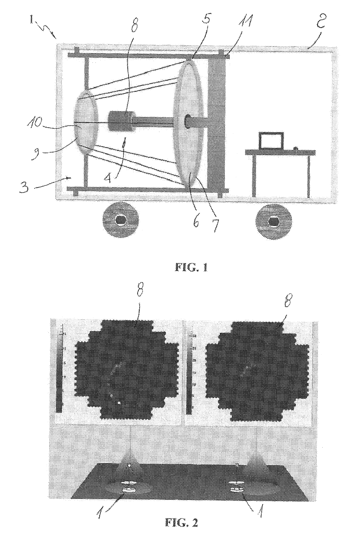
[0040]With reference to the annexed figures they show a preferred but not exclusive configuration of an apparatus for non-invasive inspection of solid bodies by muon imaging.

[0041]Particularly FIG. 1 schematically shows a preferred arrangement of an apparatus of the movable type, generally denoted by 1, namely mounted into a movable structure 2 such to be easily transported and placed in different detection areas. The apparatus 1 thus can be used both for 2D radiography and 3D tomography, possibly in a system comprising two or more apparatuses according to the invention, not necessarily similar to each other.

[0042]The apparatus 1 essentially comprises a receiver 3 adapted to intercept a Cherenkov radiation from a muon flux associated with cosmic rays passing through a portion of a body to be inspected, sensor means 4 adapted to detect the amount of Cherenkov radiation associated with the muon flux and electronic processing means, not visible since they are embedded into the mechanic...


PUM


Abstract

An apparatus for non-invasive inspection of solid bodies by muon imaging, comprising a receiver (3) adapted to intercept a muon flux associated with cosmic rays passing through a portion of a body to be inspected, sensor means (4) adapted to detect the amount of photons or Cherenkov radiation associated with the intercepted muon flux, electronic processing means adapted to reconstruct energy and direction of the muon flux incident the portion of the body to be inspected to calculate the local density thereof. The receiver (3) comprises an optical device (5) provided with at least one receiving surface (6) having reflecting and / or diffractive properties adapted to convey the Cherenkov radiation associated with muons toward the sensor means (4), these latter comprising a multipixel detection chamber (8) adapted to provide an annular image of the muon having radius and position variable as a function of the energy and direction of muon flux.

Description

TECHNICAL FIELD[0001]The present invention has application in the technical field of measuring instruments and it relates to an apparatus for non-invasive inspection of solid bodies by muon imaging usable in civil engineering, archeology, volcanology, tectonics and everywhere a radiographic and / or tomographic non-destructive inspection of geological and / or engineering structures, even of large dimensions, is necessary.[0002]The invention further relates to a method for non-invasive inspection by muon imaging implementable by said apparatus.PRIOR ART[0003]Tomographic investigations based on “tracking” techniques are known which exploit the detection of energy associated to charged particles of cosmic rays passing through a material to be investigated such to perform non-invasive inspections.[0004]Such techniques are based on displaying the trajectory of the particle that while passing through detection planes, usually scintillating planes, produce an electric pulse that, once suitabl...

Claims


Application Information

Patent Timeline
Patent Type & Authority Patents(United States)
IPC IPC(8): G01V5/00
CPCG01V5/0016G01V5/005
Inventor CATALANO, OSVALDOCONCONI, PAOLOCUSUMANO, GIANCARLODEL SANTO, MELANIALA ROSA, GIOVANNIMACCARONE, MARIA CONCETTAMINEO, TERESAPARESCHI, GIOVANNISOTTILE, GIUSEPPE
Owner INST NAT DI ASTROFISICA INAF
Why Eureka
Try Eureka