Device and method for separating carbon dioxide from a gas stream, in particular from a flue gas stream, comprising a cooling water system

a technology of carbon dioxide and cooling water system, which is applied in the direction of separation process, emission prevention, gearing, etc., can solve the problems of high capital and operating costs, high noise emissions, etc., and achieve the effect of simple implementation

Active Publication Date: 2020-02-25
SIEMENS ENERGY GLOBAL GMBH & CO KG
View PDF15 Cites 0 Cited by
  • Summary
  • Abstract
  • Description
  • Claims
  • Application Information

AI Technical Summary

Benefits of technology

A first object of the invention is to provide a very inexpensive possibility which is very simple to implement in process and apparatus terms for cooling the apparatus components used in a removal apparatus for carbon dioxide.
A second object of the invention is to provide a process for removing carbon dioxide, in which the required cooling of the fluid streams is very inexpensive and efficient.
Overall, the targeted recovery, purification and possible storage of the offgas component water and its subsequent utilization contributes to more efficient cooling of the removal process for carbon dioxide from gas streams. For this reason, not only a saving in capital and operating costs but at the same time also a reduction in the required construction area and noise emissions can be realized for the air coolers used. In addition, targeted generation of cooling water on site allows the use of water-cooled cooling units even at sites without direct access to water.
In an advantageous embodiment of the invention, the treatment unit is hydrodynamically connected via a feed line to the condensate side of the gas cooler. The feed line can be connected directly to the gas cooler and makes it possible for at least a substream of the water obtained in the gas cooler to be fed to the treatment unit. The offtake of the water obtained from the gas cooler is advantageously carried out continuously in order to keep the amount of water required for cooling the gas stream within the gas cooler constant during operation. The water obtained as condensate from the flue gas mixes with the water used for cooling the gas stream in a typical flue gas cooler. The amount of water taken off here is, in particular, dependent on the amount of water condensed out of the gas stream or the flue gas by cooling. In other words, the amount of water taken off is essentially proportional to the amount of water condensed out of the flue gas.
A further discharge line of the pressure vessel is also advantageously connected to a feed line of the absorber. In this way, the liquid scrubbing medium can be recirculated as a second substream from the pressure vessel to the absorber. As a result of the gas phase being separated off beforehand as first substream, the scrubbing medium is virtually completely freed of absorbed carbon dioxide after passage through the pressure vessel.
Such a process allows wastewater from a gas cooler used for cooling gas streams, which has hitherto been discarded unutilized, to be purified and subsequently used in a targeted manner for efficient cooling of fluid streams and / or apparatus components used in the removal process for carbon dioxide.

Problems solved by technology

However, in such air coolers, large cooling areas and high-performance blowers are necessary because of the high gas-side heat transfer resistance, so that air coolers have a correspondingly large space requirement and cause high noise emissions and also high capital and operating costs.
However, the above-described disadvantages are accepted because of the lack of alternatives.

Method used


Image

  • Device and method for separating carbon dioxide from a gas stream, in particular from a flue gas stream, comprising a cooling water system

Examples


Embodiment Construction

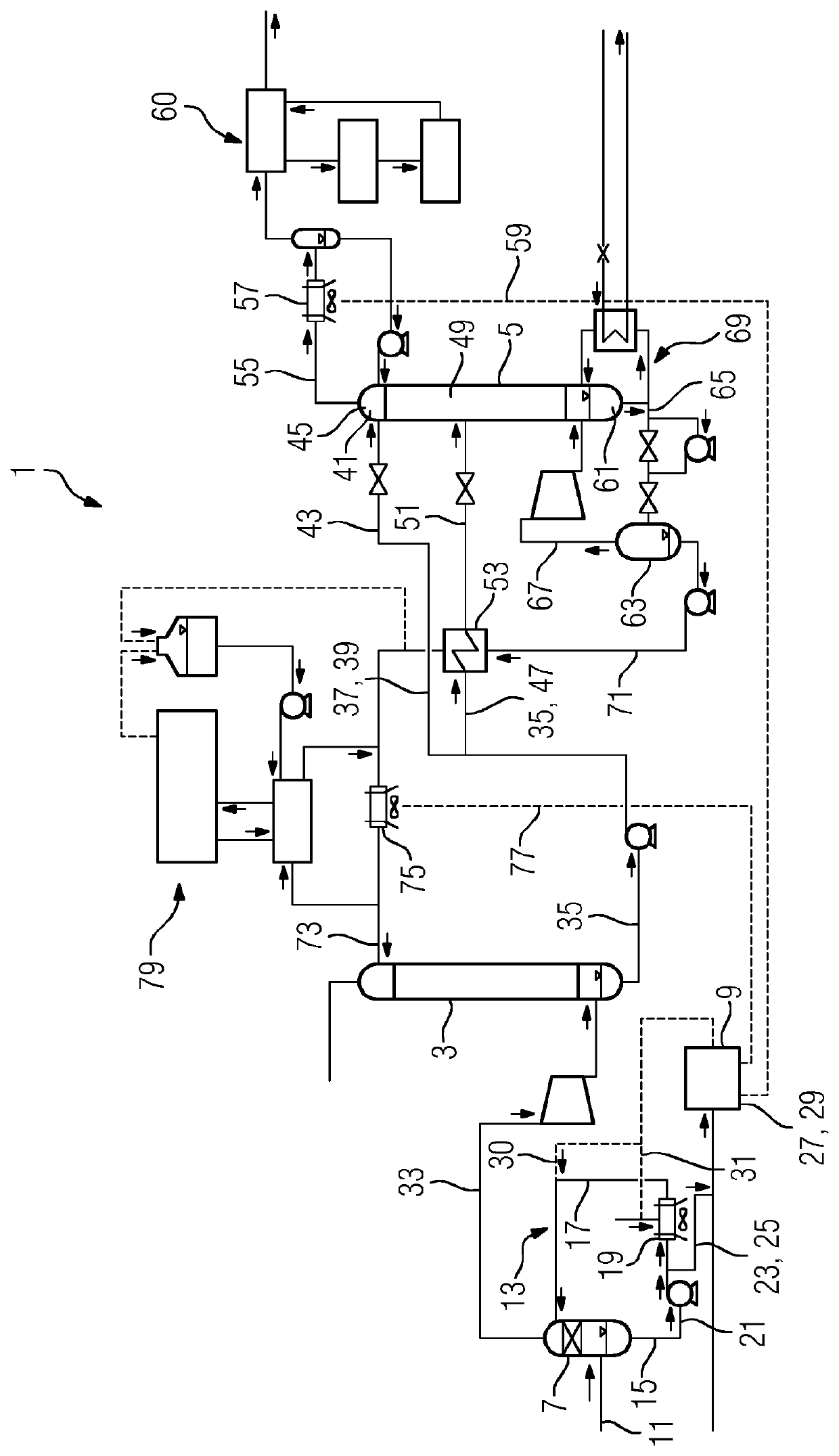
The sole FIGURE shows a removal apparatus 1 for carbon dioxide from a flue gas stream. The removal apparatus 1 comprises an absorber 3 and a desorber 5 which is hydrodynamically connected to the absorber 3. A gas cooler 7 configured as flue gas cooler, to which a treatment unit 9 for water is assigned, is located hydrodynamically upstream of the absorber 3.

In order to purify flue gas, which is obtained, for example, as combustion offgas in the combustion of fossil fuels in power stations, and in particular to separate the carbon dioxide present in the flue gas from the flue gas, a flue gas stream is firstly fed via a flue gas line 11 to the removal apparatus 1. The flue gas flows via the flue gas line 11 into the flue gas cooler 7 which is configured as a direct contact cooler and is operated using water as coolant. The flue gas is cooled in the flue gas cooler 7 before it is fed to the absorber 3 of the removal apparatus 1.

The flue gas cooler 7 itself is installed in a coolant circ...


PUM

PropertyMeasurementUnit
surface temperatureaaaaaaaaaa
heataaaaaaaaaa
resistanceaaaaaaaaaa

Abstract

A device for separating carbon dioxide from a gas stream, in particular from a flue gas stream, includes an absorber for separating the carbon dioxide from the gas stream by means of a washing medium, a desorber which is fludically connected to the absorber to release the absorbed carbon dioxide from the washing medium, a gas cooler which is fludically connected upstream of the absorber to cool the gas stream, and a processing unit which is connected downstream of the gas cooler and which is equipped and designed to clean water from the gas cooler. A method separates carbon dioxide from a gas stream.

Description

CROSS REFERENCE TO RELATED APPLICATIONSThis application is the US National Stage of International Application No. PCT / EP2015 / 056239 filed Mar. 24, 2015, and claims the benefit thereof. The International Application claims the benefit of German Application No. DE 102014206630.1 filed Apr. 7, 2014. All of the applications are incorporated by reference herein in their entirety.FIELD OF INVENTIONThe invention relates to a removal apparatus for carbon dioxide from a gas stream, in particular from a flue gas stream. Furthermore, the invention relates to a process for removing carbon dioxide from a gas stream, in particular from a flue gas stream.BACKGROUND OF INVENTIONIn view of climatic changes, it is a global objective to reduce the emission of pollutants into the atmosphere. This applies particularly to the emission of carbon dioxide (CO2) which accumulates in the atmosphere, hinders radiation of heat from the earth and thus leads, as greenhouse effect, to an increase in the surface te...

Claims


Application Information

Patent Timeline
Patent Type & Authority Patents(United States)
IPC IPC(8): B60K35/00B01D53/18F16H25/20F16H19/04C02F1/44B01D53/14F23J15/04B01D61/02B60K37/02C02F103/18
CPCB01D61/025B01D53/1425C02F1/441F23J15/04B01D53/1475B01D53/18B01D2258/0283Y02C10/06Y02A50/2342F23J2215/40B01D2259/65B01D2257/504F23J2219/40Y02E20/326C02F2103/18Y02E20/32Y02A50/20Y02C20/40
Inventor HÄFNER, BENJAMINREICHL, ALBERTROGALINSKI, TIMSCHRAMM, HENNINGWEBER, JÖRG
Owner SIEMENS ENERGY GLOBAL GMBH & CO KG
Why Eureka
Try Eureka