Brake control device, brake control method, train, and program
a technology of brake control and control device, which is applied in the direction of regenerative braking, braking systems, transportation and packaging, etc., can solve the problem of high overhead wire voltage, and achieve the effect of reducing the response lag of air brakes, improving the accuracy of tracking a target speed, and reducing the cos
- Summary
- Abstract
- Description
- Claims
- Application Information
AI Technical Summary
Benefits of technology
Problems solved by technology
Method used
Image

Examples
first embodiment
[0031]Hereinafter, a brake control device for a train according to a first embodiment of the present invention will be described with reference to FIGS. 1 to 3.
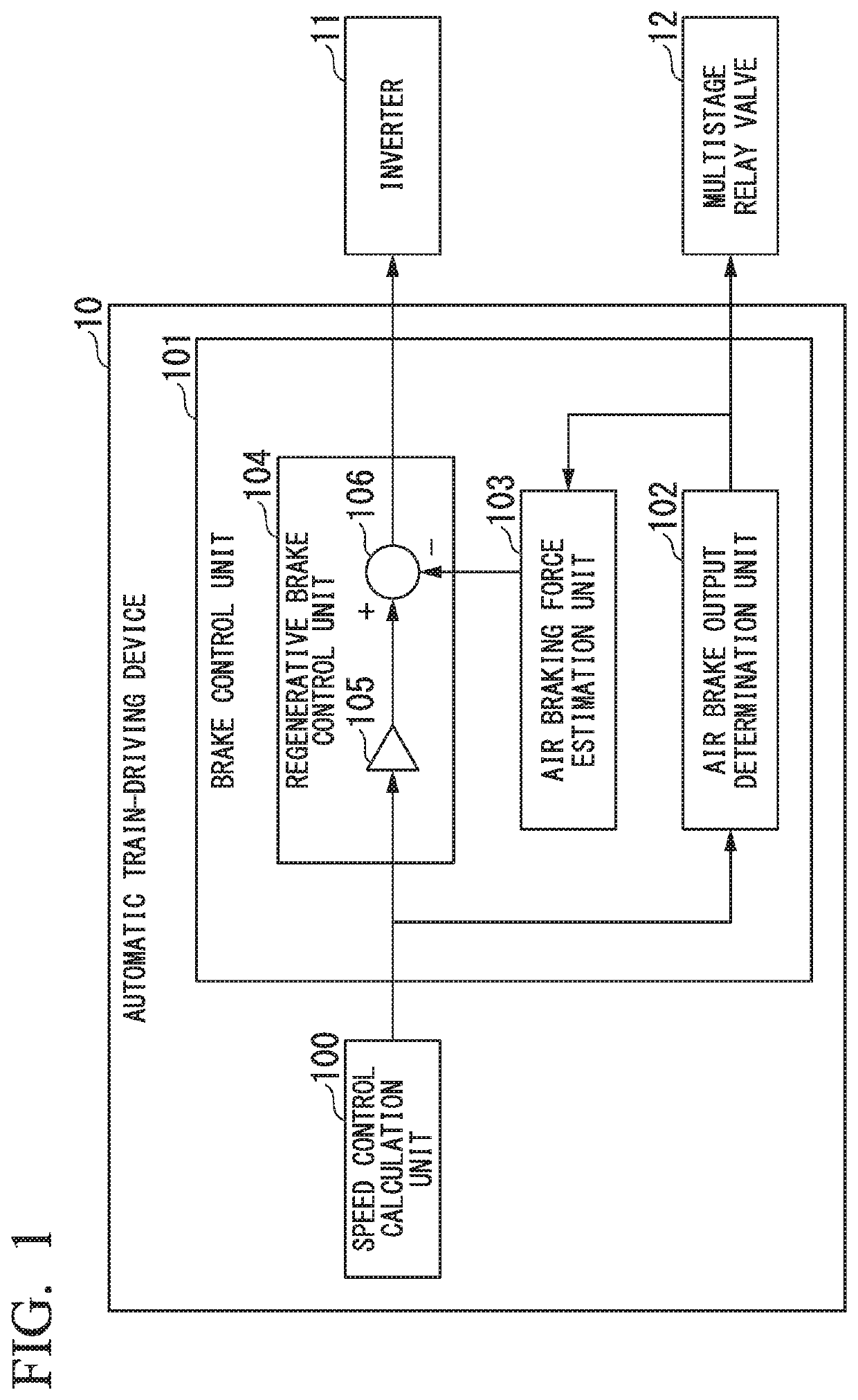
[0032]FIG. 1 is a functional block diagram illustrating an example of a brake control device according to a first embodiment of the present invention.
[0033]An automatic train-driving device 10 is a device that is mounted on a train and automates driving of the train. As illustrated in FIG. 1, the automatic train-driving device 10 includes a speed control calculation unit 100 and a brake control unit 101. The speed control calculation unit 100 occasionally calculates a target speed of the train when automatically driving the train. For example, when the train approaches a train station or a train traveling in front of the train, the speed control calculation unit 100 calculates a target deceleration and outputs the target deceleration to the brake control unit 101. The brake control unit 101 performs brake control based on the...
second embodiment
[0064]Next, a brake control device for a train according to a second embodiment of the present invention will be described with reference to FIGS. 4 to 8.
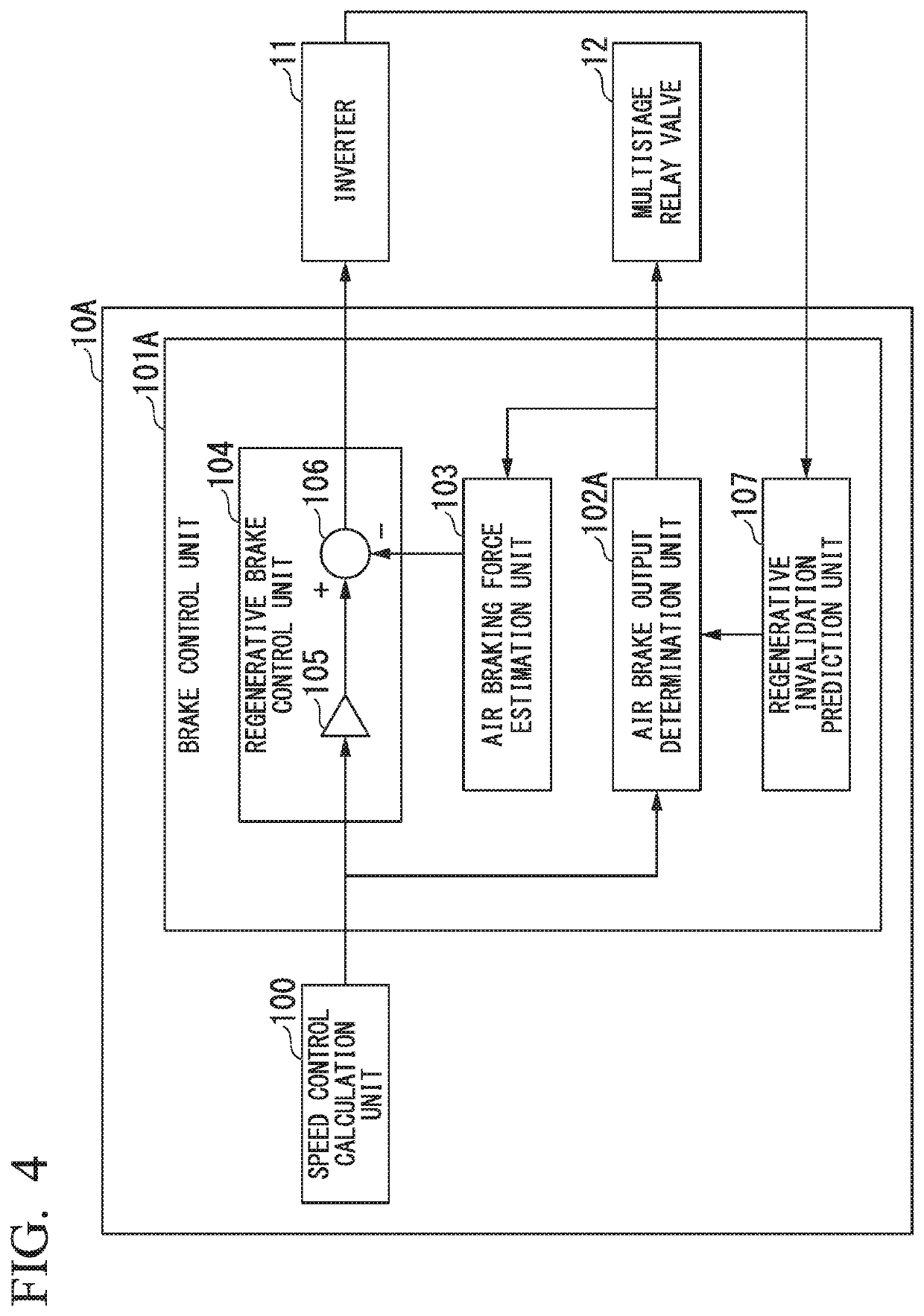
[0065]FIG. 4 is a functional block diagram illustrating an example of the brake control device according to the second embodiment of the present invention.
[0066]In a configuration according to the second embodiment, functional units the same as functional units constituting the automatic train-driving device 10 according to the first embodiment of the present invention are denoted by the same reference numerals, and description thereof will be omitted.
[0067]An automatic train-driving device 10A in the second embodiment includes a speed control calculation unit 100 and a brake control unit 101A. The brake control unit 101A includes an air brake output determination unit 102A, an air braking force estimation unit 103, a regenerative brake control unit 104, and a regeneration invalidation prediction unit 107. The regenerative brake co...
third embodiment
[0094]Next, a brake control device for a train according to a third embodiment of the present invention will be described with reference to FIGS. 9 to 10.
[0095]FIG. 9 is a functional block diagram illustrating an example of the brake control device according to the third embodiment of the present invention.
[0096]In a configuration according to the third embodiment, functional units that are the same as the functional units constituting the automatic train-driving device 10 according to the first embodiment of the present invention and the automatic train-driving device 10A according to the second embodiment are denoted by the same reference numerals, and description thereof will be omitted.
[0097]An automatic train-driving device 10B in the third embodiment includes a speed control calculation unit 100 and a brake control unit 101B. The brake control unit 101B includes an air brake output determination unit 102A, an air braking force estimation unit 103B, a regenerative brake control...
PUM
 Abstract
Description
Claims
Application Information
 - R&D
- Intellectual Property
- Life Sciences
- Materials
- Tech Scout
- Unparalleled Data Quality
- Higher Quality Content
- 60% Fewer Hallucinations
Browse by: Latest US Patents, China's latest patents, Technical Efficacy Thesaurus, Application Domain, Technology Topic, Popular Technical Reports.
© 2025 PatSnap. All rights reserved.Legal|Privacy policy|Modern Slavery Act Transparency Statement|Sitemap|About US| Contact US: help@patsnap.com