Tubular foundation for onshore wind turbine generators
What is AI technical title?
AI technical title is built by Patsnap AI team. It summarizes the technical point description of the patent document.
a technology for wind turbine generators and tubular foundations, which is applied in the direction of foundation engineering, wind motor supports/mounts, construction, etc., can solve the problems of stiffness, structure would be difficult to transport to wind farm sites, and the foundation cannot support light superstructures, etc., to save construction time, simplify construction procedures, and improve construction accuracy
Active Publication Date: 2020-08-11
MONTANA SYST INC
View PDF29 Cites 6 Cited by
Summary
Abstract
Description
Claims
Application Information
AI Technical Summary
This helps you quickly interpret patents by identifying the three key elements:
Problems solved by technology
Method used
Benefits of technology
Benefits of technology
The present invention provides a tubular rivet-like foundation that is simple, cost-efficient, environment-friendly, and suitable for most subsurface conditions. The foundation follows the principles of soil mechanics and the loading distribution among rigid, fix-connected structural members. The design engineers are familiar with the forms and features of the foundation and can use standard codes for design purposes. The construction procedure is simplified and the construction time is saved. The present foundation is relatively small in size, and the removal of the earth surfacevegetation is small, making it environment-friendly. The technical effects of the present invention include savings in construction cost of about 40% compared to industry-widely used invert T-type spread foundation under the same loadings with the same site conditions and its being more durable, reliable, and cost-efficient.
Problems solved by technology
The foundation embedded in the ground, but the precast sections impose size limitations and thus the foundation can only support light superstructures which subject to relatively small overturning moment.
The Upson's structure is pre-stressed reinforced concrete structure and not suitable for use as foundations for wind turbine generators which subject to tremendous overturning moment.
The joint means connecting the pipes are not rigid connection, which could cause problems in stiffness.
And, the structure would be difficult to transport to wind farm site.
Obviously, the Rensaa's method is rather for construction, and the Rensaa's entire structure is not suitable for use as a large foundation for tall superstructure like wind turbine generators.
Accordingly, the O'Neil structure is not capable of being used to support superstructure subject to high overturning moment or being placed under high unit compressive loading.
Accordingly, the Kinnan's structure is not capable of being used to support superstructure subject to high overturning moment or being placed under high unit compressive loading.
The Lin's invented construction method and device is expensive, and the construction process is less practical.
The Medieros' foundation is complicated in construction, and thus not cost-efficient.
Moreover, the welding connecting the gravity piles is vulnerable to high fatigue, cyclic loadings provided by wind turbine generators.
Such separate plates and anchors may have a risk to be pulled out when the overturning moment is large.
Thus, the Tinsley's foundation is not capable of supporting superstructures such as wind turbine generators which subject to high overturning moment.
The technique is helpful to increase the lifetime of the foundation but not improving the mechanical behavior of the foundation by inventing forms and features.
Method used
Image
Click on the blue label to locate the original text in one second.
Reading with bidirectional positioning of images and text.
Examples
Embodiment Construction
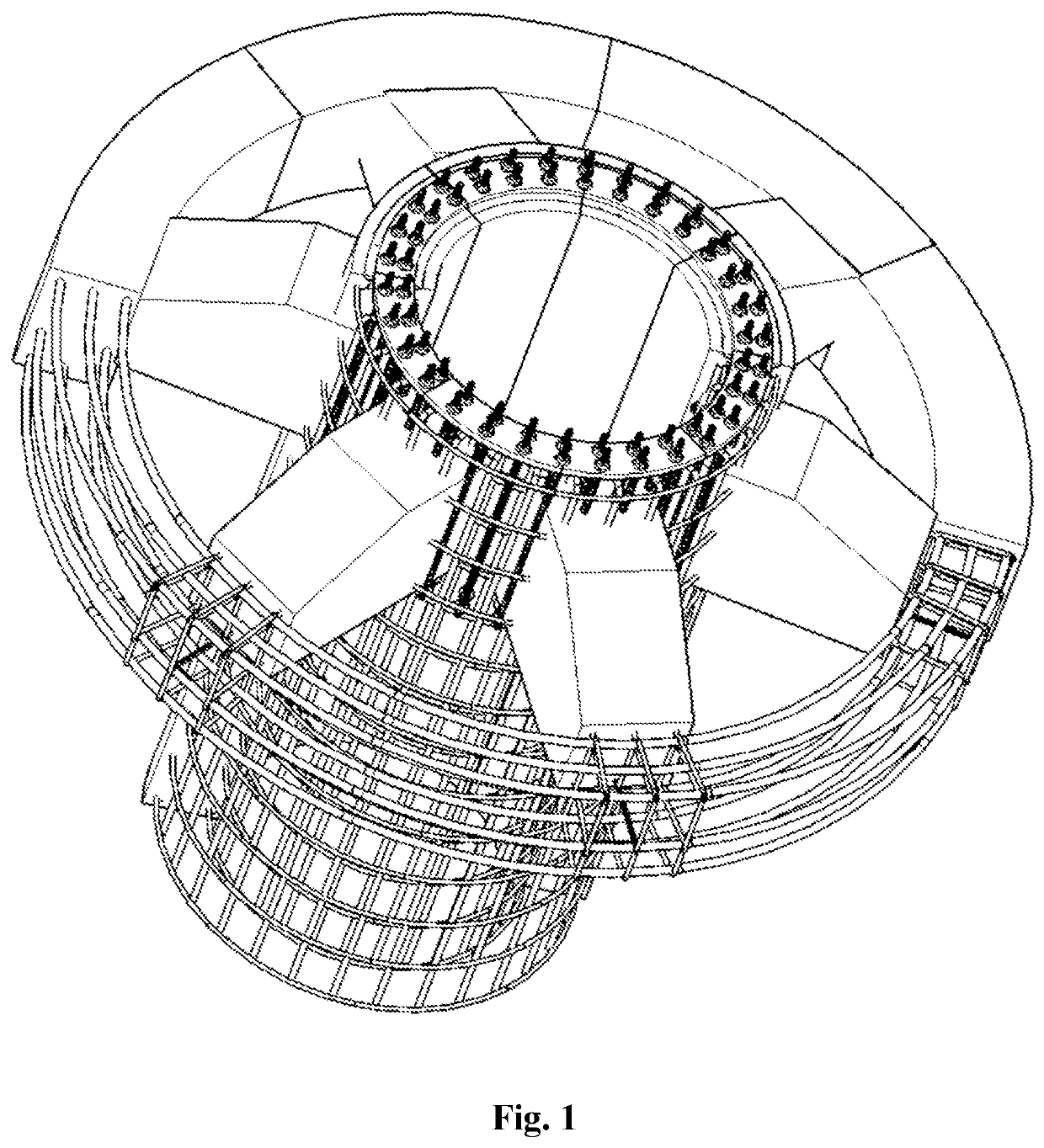
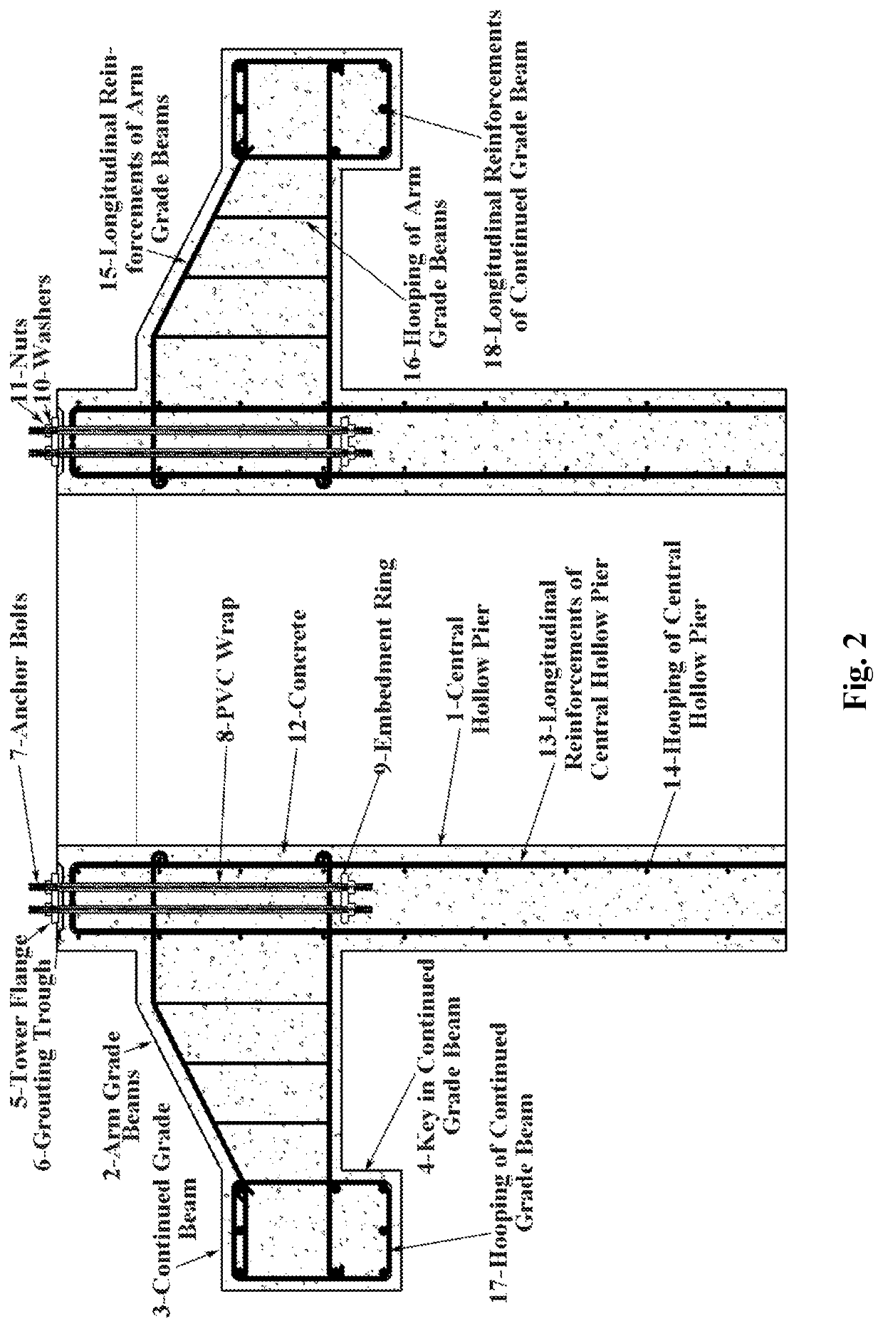
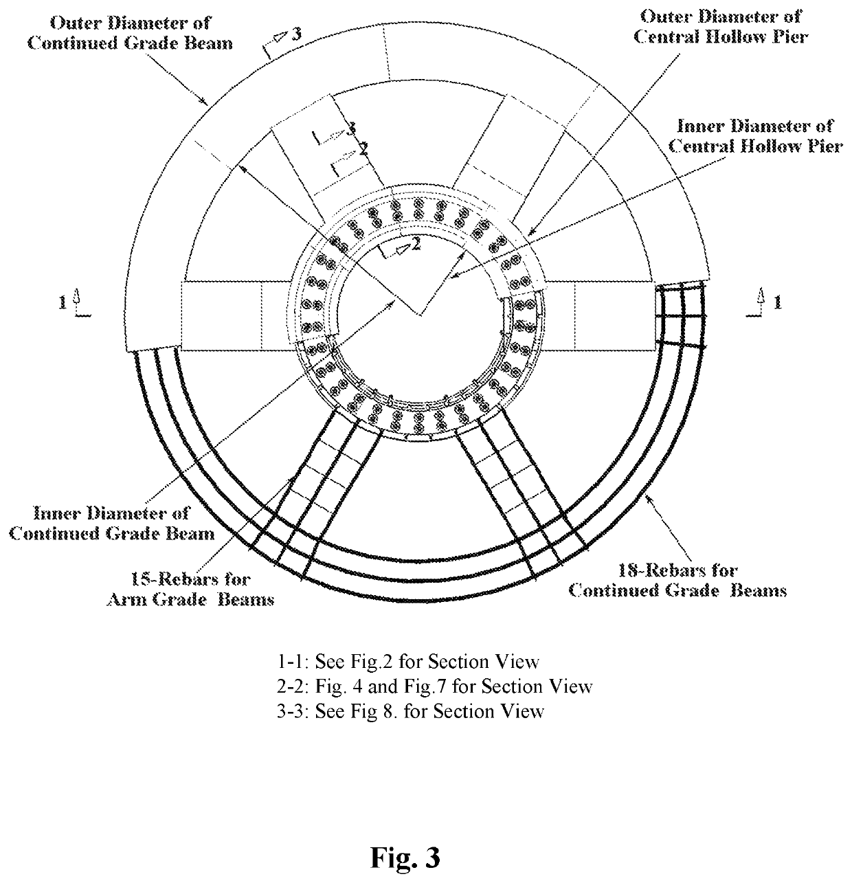
[0069]Referring specifically to the drawings, FIG. 1 is a 3-D illustration for the present foundation, and FIG. 2 designates the top plan view of the invented foundation. FIGS. 2 to 8 show the details for the foundation. FIG. 2 designates a vertical sectional view of the foundation, the numerals in FIG. 2 show that the foundation comprises four major structural members, central hollow pier 1, arm grade beams 2, continued grade beam 3, and continued shear key 4 built below the continued grade beam 3. The configuration of the central hollow pier 1 matches the tower base flange 5, which is also shown on FIGS. 1 and 2. The inner and outer diameters of the central hollow pier 1 typically range from 10 feet to 16 feet for wind turbine generator foundation to accommodate the base flange 5 which sits in the grouting trough 6 shown in FIG. 2. The grouting trough 6 is constructed as a groove on the top of the central hollow pier 1. The depth of the grouting trough 6 typically ranges 2 to 5 in...
PUM
Abstract
Embodiments of the present foundation for wind turbine generators comprise four structural members: a relatively long central hollow pier, several arm grade beams, a continued grade beam and a continued shear key. The central hollow pier positions in the center of the foundation system, arm grade beams are arranged evenly in radial direction and extend from the pier to the continued grade beam. Continued grade beam is arranged circumferentially in outer periphery and the continued shear key is built below it. Arm grade beams have a varied section with the far end embedding into ground. The top of the continued grade beam matches the top of arm grade beams, while the continued shear key embeds deeper into ground. All structural members are constructed of cast-in-place concrete reinforced with rebars, and all connections are fixed and rigid. The present foundation uses the ground to shape and form the structural members, no formwork, backfilling and compaction is needed.
Description
REFERENCES CITEDU.S. Patent Documents[0001]U.S. Pat. No. 1,048,993 Dec. 31, 1912 C. Meriwether[0002]U.S. Pat. No. 2,347,624 Apr. 24, 1942 B. J. Schwendt[0003]U.S. Pat. No. 2,706,498 Nov. 13, 1950 M. M. Upson[0004]U.S. Pat. No. 2,724,261 Nov. 22, 1955 E. M. Renssa[0005]U.S. Pat. No. 3,186,181 Jun. 1, 1965 R. K. Show et al.[0006]U.S. Pat. No. 3,382,680 May 14, 1968 Tamio Takano[0007]U.S. Pat. No. 3,600,085 Aug. 24, 1971 F. Vanich[0008]U.S. Pat. No. 3,842,608 Oct. 22, 1974 L. A. Turzzillo[0009]U.S. Pat. No. 3,963,056 Jun. 15, 1976 A. Shibuya et al.[0010]U.S. Pat. No. 4,228,627 Oct. 21, 1980 J. C. O'Neill[0011]U.S. Pat. No. 4,618,287 Oct. 21, 1986 F. Kinnan[0012]U.S. Pat. No. 4,842,447 Jun. 27, 1989 J. J. Lin[0013]U.S. Pat. No. 5,228,806 Jul. 20, 1993 C. De Medieros[0014]U.S. Pat. No. 5,379,563 Jan. 10, 1995 C. R. Tinsley[0015]U.S. Pat. No. 5,586,417 Dec. 24, 1996 A. Henderson[0016]U.S. Pat. No. 5,826,387 Oct. 27, 1998 A. Henderson[0017]U.S. Pat. No. 7,533,505 May 19, 2009 A. Henderson[...
Claims
Application Information
Patent Timeline
Application Date:The date an application was filed.
Publication Date:The date a patent or application was officially published.
First Publication Date:The earliest publication date of a patent with the same application number.
Issue Date:Publication date of the patent grant document.
PCT Entry Date:The Entry date of PCT National Phase.
Estimated Expiry Date:The statutory expiry date of a patent right according to the Patent Law, and it is the longest term of protection that the patent right can achieve without the termination of the patent right due to other reasons(Term extension factor has been taken into account ).
Invalid Date:Actual expiry date is based on effective date or publication date of legal transaction data of invalid patent.

