Collapsible support structure for a removable electronic device

a technology for electronic devices and support structures, which is applied in the direction of machine supports, mechanical devices, stands/trestles, etc., can solve the problems of time-consuming, delayed project progress, and difficult for a group or user to access, update or submit documents

Active Publication Date: 2021-03-09
ROK TECH LLC
View PDF5 Cites 2 Cited by
  • Summary
  • Abstract
  • Description
  • Claims
  • Application Information

AI Technical Summary

Benefits of technology

[0025]It is within the scope of the current invention for a barrier member to be removably connected to the corners of the mounting bracket when an electronic device is retained within the mounting bracket. The barrier member protects the electronic device from the force of being impacted by surrounding environmental, accidental, and / or damage factors during use and / or during storage.

Problems solved by technology

The status relating to any changes, amendments, additions, deletions, or updates to the construction documents are notated and delivered by courier to the receiving party, which can be time consuming and may delay project progress.
It may be difficult for a group or users to access and update or submit documents through the small size of a graphic user interface of a personal electronic device.
The problem with this existing construction productivity method is the bulkiness of the toolbox, which inhibits the ease of transporting the electronic documents from each construction site.
Further, the computer of current methods located on the toolbox often gets damaged when exposed to the elements such as rain, snow, sunlight, or construction debris.
Finally, a computer placed on a toolbox is susceptible to theft because of the lack of securing means to secure the computer onto the toolbox.

Method used


Image

  • Collapsible support structure for a removable electronic device
  • Collapsible support structure for a removable electronic device
  • Collapsible support structure for a removable electronic device

Examples


Embodiment Construction

[0047]In the following detailed description of the preferred embodiments, reference is made to the accompanying drawings, which form a part hereof, and within which are shown by way of illustration specific embodiments by which the invention may be practiced. It is to be understood that other embodiments may be utilized and structural changes may be made without departing from the scope of the invention.

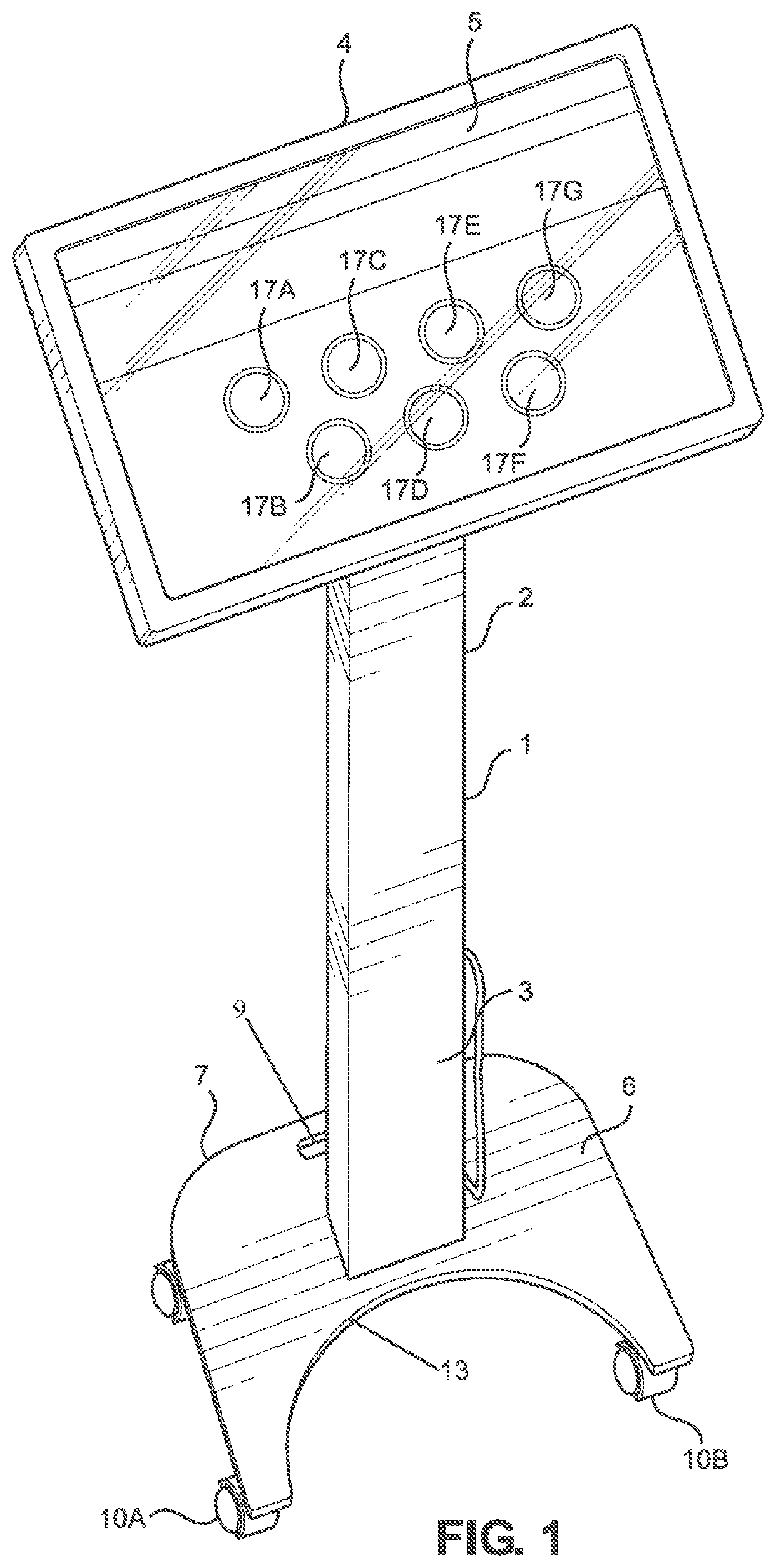
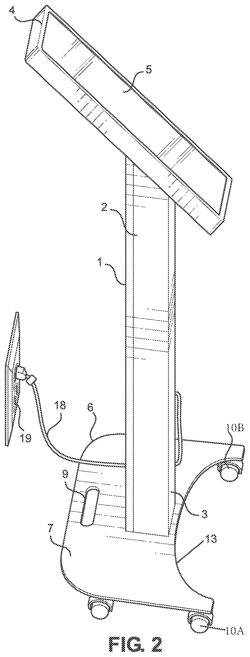
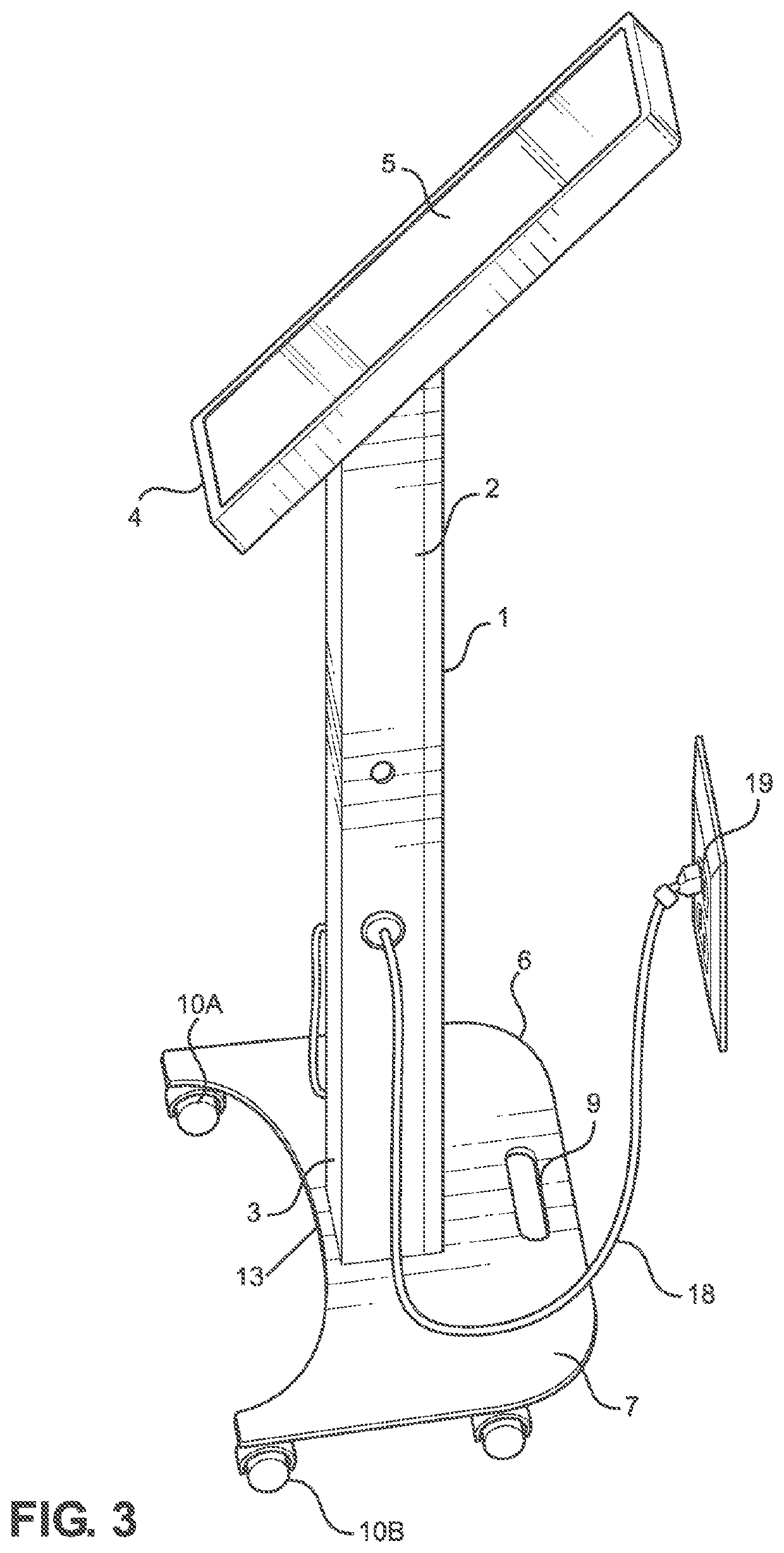
[0048]It will now be seen, referring to FIGS. 1-4, novel support structure 1 for electronic device 4 has touch screen 5 (FIGS. 1-3). FIG. 1 best illustrates touch screen 5 having application icons 17A-17F such as different construction related apps configured for a user to activate through the graphic user interface of touch screen 5. It is within the scope of this invention for a programmer to program a predetermined selection of desirable apps that are to be accessible to the users of electronic device 4. FIGS. 1-3 illustrate support structure 1 having first end 2 located opposite ...


PUM


Abstract

A collapsible support structure for a removable electronic device. The electronic device having a touch screen configured for a user to access at least one predetermined construction document and/or application is removably connected to the support structure. The electronic device may be retained in a housing configured to be water resistant and/or impact resistant. The support structure may have a locking mechanism configured for an authorized user to gain access to remove the electronic device from the support structure, thereby, preventing an unauthorized user from gaining access for removal of the electronic device from the support structure. The support structure is configured to be foldable in a closed orientation during storage. The support stand may have a plurality of casters connected thereto.

Description

CROSS REFERENCE TO RELATED APPLICATIONS[0001]This application is a Continuation-In-Part Utility Application entitled, “Collapsible Support Structure For A Removable Electronic Device”, which claims priority to co-pending U.S. patent application Ser. No. 16 / 705,366 filed Dec. 6, 2019, entitled, “Collapsible Support Structure For A Removable Electronic Device”.BACKGROUND OF THE INVENTION1. Field of the Invention[0002]This invention relates, generally, to a collapsible support structure for a removable electronic device. More particularly, it relates to a support structure for an electronic device having a touch screen that is capable of receiving and locking an electronic device in position and being oriented in an upright orientation during use, as well as folding into a closed orientation during storage.2. Background Art[0003]Traditional methods of conducting construction productivity is organized by providing a user including, but not limited to, an engineer, a construction worker,...

Claims


Application Information

Patent Timeline
Patent Type & Authority Patents(United States)
IPC IPC(8): F16M11/00F16M11/04F16M11/10F16M11/42
CPCF16M11/046F16M11/10F16M11/42F16M2200/024F16M2200/028F16M11/041
Inventor MCCALL, TODD
Owner ROK TECH LLC
Why Eureka
Try Eureka