Scroll compressor with oil separator

a compressor and oil separator technology, applied in the direction of machines/engines, rotary/oscillating piston pump components, liquid fuel engines, etc., can solve the problems of increasing the reducing the reliability of the compressor, and the degree of oil separation is not constant, so as to prevent frictional loss or abrasion due to an oil shortage in the compressor and improve the oil separation effect. , the effect of more inertia

Active Publication Date: 2021-07-06
LG ELECTRONICS INC
View PDF11 Cites 0 Cited by
  • Summary
  • Abstract
  • Description
  • Claims
  • Application Information

AI Technical Summary

Benefits of technology

[0014]Therefore, an aspect of the detailed description is to provide a scroll compressor that is capable of separating refrigerant and oil within a casing and of minimizing the driving of the oil out of the casing along with the refrigerant.
[0015]Another object of the present invention is to provide a scroll compressor that is capable of being less influenced by an operation speed of an electric motor and thus increasing an oil separation effect in all operation bands.

Problems solved by technology

However, the oil that flows into the upper space is not sufficiently separated from the refrigerant, and thus the oil is driven out of the compressor, along with the refrigerant.
As a result, there is a problem in that an increasing oil shortage in the compressor is caused.
Furthermore, in the lower compressor type of scroll compressor in the related art, in a case where an inverter motor in which an operation speed of the electric motor is variable is used, the degree of the oil separation is not constant.
There is a problem in that this inconstancy decreases the reliability of the compressor.
However, the dependence on the centrifugal force caused by the rotator makes a satisfactory oil separation effect difficult to expect.
In a case where the electric motor operates at an intermediate speed (approximately 60 to 90 Hz in the case of the compressor), there is a limitation in that, characteristically, the oil separation effect that results from the centrifugal force is more decreased.
Furthermore, in the lower compression type of scroll compressor in the related art, a refrigerant discharge path and an oil collection path run in opposite directions and thus interfere with each other.
This causes an oil shortage within the casing.
Thus, frictional loss or abrasion occurs due to the oil shortage in the compression unit.
Thus, there occurs a problem in that the oil shortage within a severe compression continues.
As a result, a severer oil shortage within the compressor continues.

Method used


Image

  • Scroll compressor with oil separator
  • Scroll compressor with oil separator
  • Scroll compressor with oil separator

Examples


Embodiment Construction

[0066]Description will now be given in detail of the exemplary embodiments, with reference to the accompanying drawings. For the sake of brief description with reference to the drawings, the same or equivalent components will be provided with the same reference numbers, and description thereof will not be repeated.

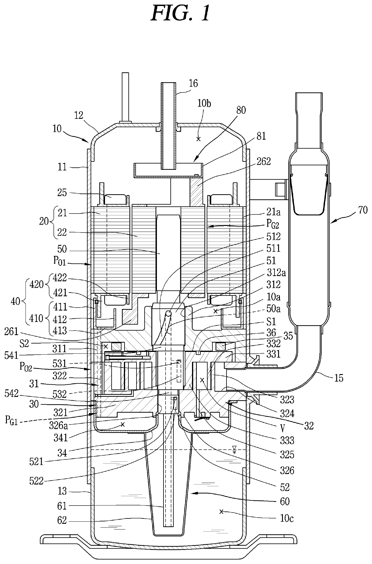
[0067]A scroll compressor according to an embodiment of the present invention will be described in detail below with reference to the accompanying drawing. For reference and convenience, as a typical example of the embodiment of the scroll compressor according to the present invention, a type of scroll compressor in which a rotation shaft overlaps a volute wrap in the same plane will be described, among lower compression types of scroll compressors in which a compression unit is positioned more downward than an electric motor. It is known that this type of scroll compressor is suitable for application in a cooling cycle system under the condition of a high pressure ratio a...


PUM


Abstract

Provided a scroll compressor including: a casing, an internal space in which is sealed; a drive motor that is configured with a stator which is located in the internal space, and a rotator which rotates within the stator, and that has an internal flow passage and an external flow passage that passes through the drive motor itself; a rotation shaft that is connected to the rotator of the drive motor; a compression unit that includes a first scroll which is provided below the drive motor, and a second scroll which is engaged with the first scroll; a discharge pipe that communicates with an upper space of the internal space, which is formed above to the drive motor; and an oil separation member that is provided between the drive motor and the discharge pipe, and from whose upper surface a space is formed to a predetermined depth.

Description

CROSS-REFERENCE TO RELATED APPLICATION[0001]Pursuant to 35 U.S.C. § 119(a), this application claims the benefit of earlier filing date and right of priority to Korean Application No. 10-2017-0059506, filed on May 12, 2017, the contents of which are incorporated by reference herein in its entirety.BACKGROUND OF THE DISCLOSURE1. Field of the Disclosure[0002]The present disclosure relates to a scroll compressor, and particularly to a compressor in which a compression unit is positioned to one side of an electric motor.2. Background of the Disclosure[0003]A scroll compressor is a compressor in which, while an orbiting motion is performed with multiple scrolls being engaged with each other, a compression chamber which includes an absorption chamber, an intermediate pressure chamber, and a discharge chamber are formed between both scrolls. This type of scroll compressor achieves not only a comparatively high compression when compared with other types of compressor, but also a stable torqu...

Claims


Application Information

Patent Timeline
Patent Type & Authority Patents(United States)
IPC IPC(8): F04C18/02F04C29/02F04C29/12F04C29/04
CPCF04C18/0215F04C29/026F04C29/028F04C29/12F04C29/045F04C23/008F04C29/005
Inventor KIM, CHEOLHWANKIM, TAEKYOUNGLEE, KANGWOOKLEE, BYEONGCHUL
Owner LG ELECTRONICS INC
Why Eureka
Try Eureka