

Cooking fume exhauster
A range hood and oil fume technology, which is applied in the direction of oil fume removal, household heating, lighting and heating equipment, etc., can solve the problems of inability to absorb oil fume and oil fume particles, affect the oil filtering effect of the oil filter device, and achieve the improvement of oil separation ability, Noise reduction effect
- Summary
- Abstract
- Description
- Claims
- Application Information
AI Technical Summary
Problems solved by technology
Method used
Image

Examples
Embodiment Construction
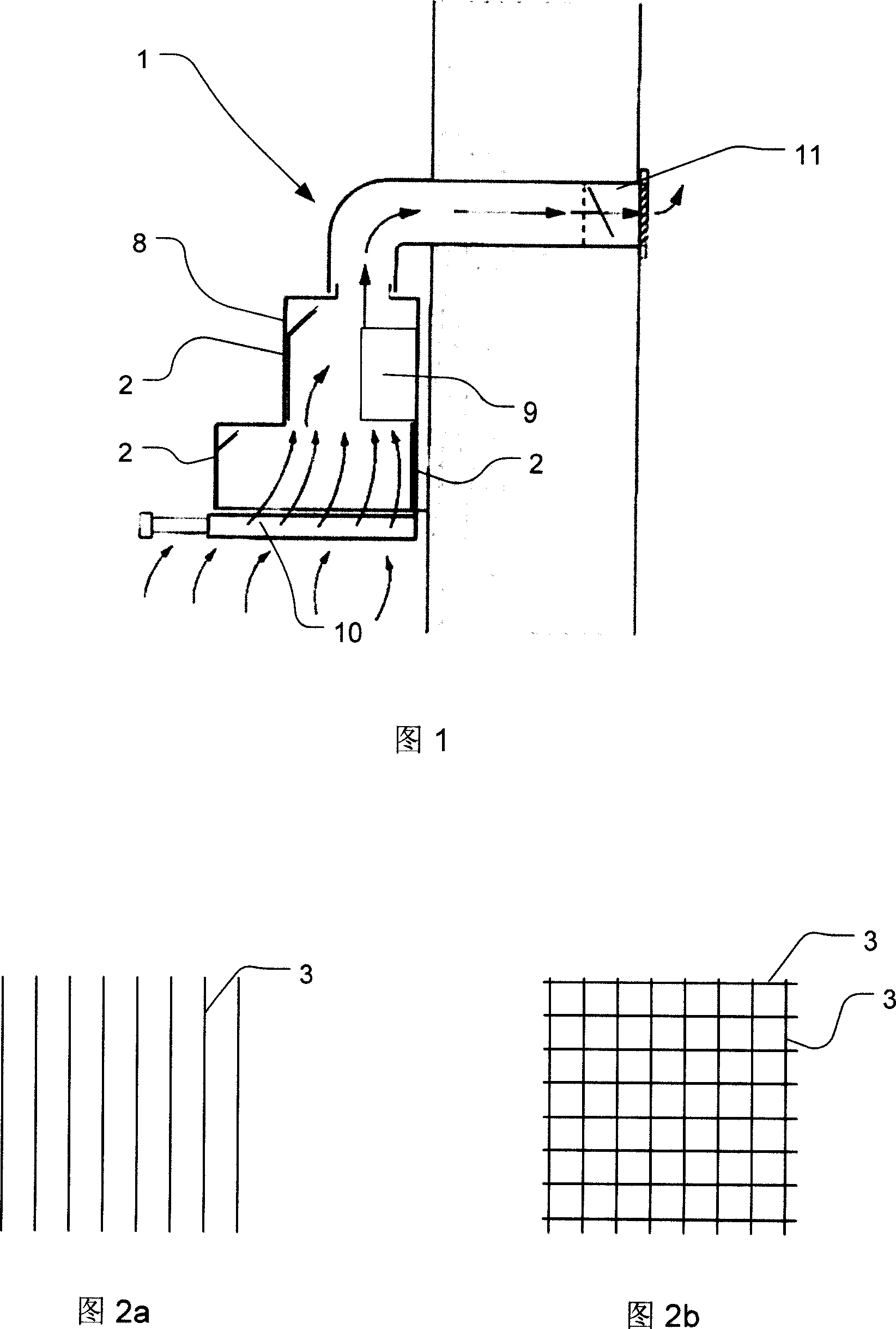
[0027] Referring to the accompanying drawings, the range hood 1 as shown in FIG. 1 includes a casing 8, an exhaust device 9 disposed in the casing 8, a filter screen 10 connected to the bottom of the casing 8, A surface element 2 arranged in the housing 8 and an exhaust port 11 of the range hood 1 .
[0028] The surface element 2 is any part of the inner wall of the housing 8 that is in contact with the cooking fume entering the range hood 1 .
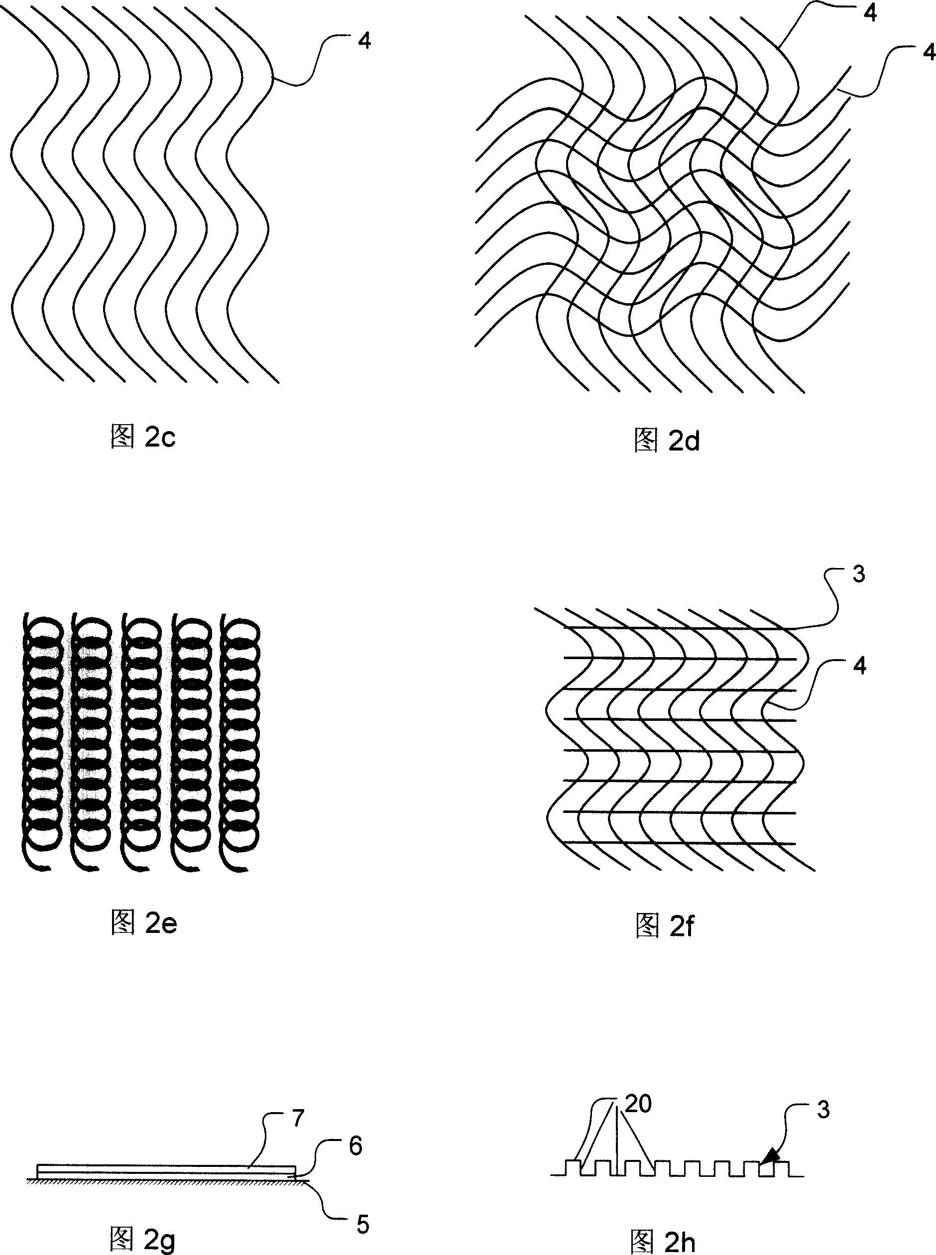
[0029] The surface element 2 is a surface 20 with an increased surface area compared to the planar structure of the inner wall of a conventional range hood. As shown in Fig. 2h, said surface area 20 of increased surface area is formed by geometrical elements 3, 4 (the geometrical elements 3, 4 shown in Fig. 2h are stripes as shown in Fig. 2a). The shape of the first and / or second geometric element is shown in Figure 2a to Figure 2e, wherein Figure 2a and Figure 2b illustrate the first and / or second geometric element in the form of str...
PUM
| Property | Measurement | Unit |
|---|---|---|
| Height | aaaaa | aaaaa |
Abstract
Description
Claims
Application Information