Air energy power machine

a power machine and air technology, applied in machines/engines, positive displacement liquid engines, lighting and heating apparatus, etc., can solve the problems of reducing underground reserves, polluting the environment, and internal combustion engines having to consume non-renewable energy oil during use, and achieve strong practicality and cleaner energy utilization.

Active Publication Date: 2021-12-21
ZHU LIN
View PDF13 Cites 0 Cited by
  • Summary
  • Abstract
  • Description
  • Claims
  • Application Information

AI Technical Summary

Benefits of technology

[0008]The present invention has novel concept, ingenious structure and strong practicality, and utilizes the energy by that the work applied to the increase of air temperature is greater than the work applied to the consumption of power through air compression so that the energy utilization is cleaner.

Problems solved by technology

The internal combustion engines have strong power, convenient use, long duration and wide range of use, but the internal combustion engines must consume the non-renewable energy oil during use.
The use of oil will greatly reduce the underground reserves of oil and pollute the environment; and the massive use of oil will cause the competition in oil resources, trigger a war and endanger human beings.
The boilers generally consume coals during use; the use of coals will more seriously pollute the environment and consume more non-renewable energies than the use of oil; and the bulk mining of coals is easy to cause mine disasters and endanger human beings.
The coal-fired power generation also consumes coals during use, thereby more seriously polluting the environment and consuming more non-renewable energies.
The construction of hydropower stations is easy to destroy the original ecology and cause earthquakes.
The wind power generation and the photovoltaic power generation do not damage the environment and consume conventional resources, but the resources are unstable and highly volatile.
For the State Grid, wind electricity and photovoltaic electricity are not high-quality electricity but garbage electricity.

Method used


Image

  • Air energy power machine

Examples


Embodiment Construction

Optimal Embodiment of the Invention

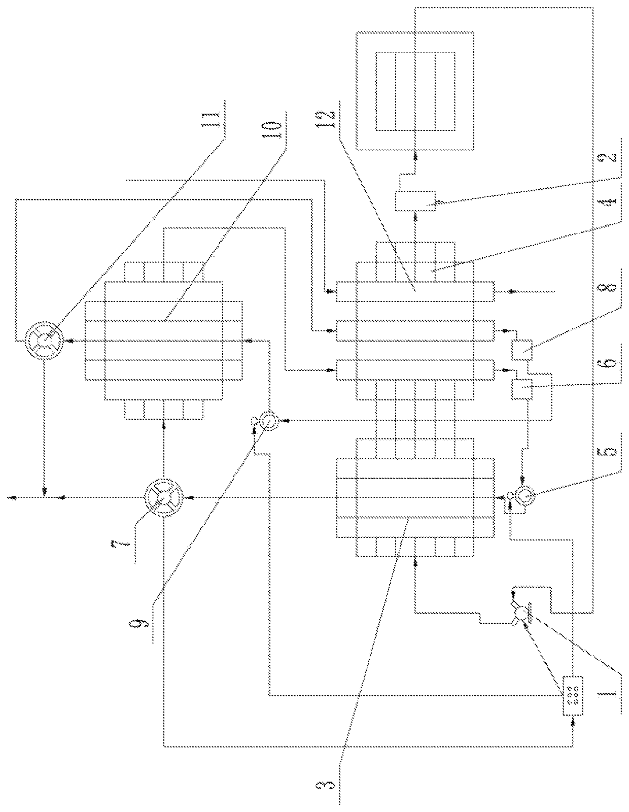
[0010]Specific embodiments of the present invention will be further described in detail below with reference to the accompanying drawings.

[0011]As shown in FIG. 1, the present invention includes an air compressor 1. An air inlet end of the air compressor 1 is connected with an air storage tank 2 through a pipeline; an air outlet end of the air compressor 1 is connected with a first heat exchanger 3 through a pipeline; a second heat exchanger 4 is connected to the right side of the first heat exchanger 3 through a pipeline; and the second heat exchanger 4 is connected with the air storage tank 2 to form a closed loop.

[0012]A first liquid pump 5 connected with the first heat exchanger 3 through a pipeline is arranged below the first heat exchanger 3; a first liquid collection tank 6 is connected to the first liquid pump 5; a first steam turbine 7 is arranged above the first heat exchanger 3; a steam inlet of the first steam turbine 7 is connected wit...


PUM


Abstract

An air energy power machine comprises an air compressor (1). An air inlet end of the air compressor is connected with an air storage tank (2) through a pipeline; an air outlet end of the air compressor is connected with a first heat exchanger (3) through a pipeline; a second heat exchanger (4) is connected to the right side of the first heat exchanger through a pipeline; the second heat exchanger is connected with the air storage tank to form a closed loop; a first liquid pump (5) connected with the first heat exchanger through a pipeline is arranged below the first heat exchanger; a first liquid collection tank (6) is connected to the first liquid pump; a first steam turbine (7) is arranged above the first heat exchanger; a steam inlet of the first steam turbine is connected with the first heat exchanger through a pipeline.

Description

CROSS-REFERENCE TO RELATED APPLICATIONS[0001]This application is a continuation of International Patent Application No. PCT / CN2019 / 081936 with a filing date of Apr. 9, 2019, designating the United States, now pending, and further claims priority to Chinese Patent Application No. 201810358389.5 with a filing date of Apr. 20, 2018. The content of the aforementioned applications, including any intervening amendments thereto, are incorporated herein by reference.TECHNICAL FIELD[0002]The present invention relates to the field of air thermal power, in particular to an air energy power machine.BACKGROUND OF THE PRESENT INVENTION[0003]The frequently-used ways to provide power and energy at present include internal combustion engines, boilers, hydropower generation, coal-fired power generation, wind power generation and photovoltaic power generation. The internal combustion engines have strong power, convenient use, long duration and wide range of use, but the internal combustion engines mus...

Claims


Application Information

Patent Timeline
Patent Type & Authority Patents(United States)
IPC IPC(8): F01K7/16
CPCF01K7/16F01K25/10F04B39/06F04B41/02F22B1/1838F01K23/04
Inventor ZHU, LINZHU, ZIQI
Owner ZHU LIN
Why Eureka
Try Eureka