Image processing device and control method therefor
a technology of image processing and control method, applied in the field of image processing technique, can solve problems such as giving users an uncomfortable feeling
- Summary
- Abstract
- Description
- Claims
- Application Information
AI Technical Summary
Benefits of technology
Problems solved by technology
Method used
Image

Examples
first embodiment
[0031]The first embodiment of an image shift device according to the present invention will be described below by taking an MR / VR system as an example.
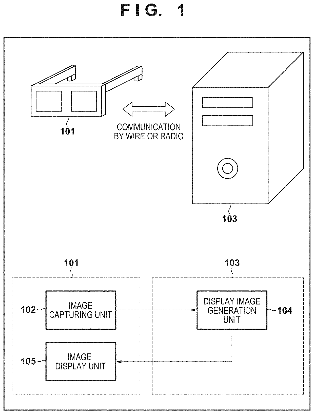
[0032]An MR system includes an HMD including an image capturing unit and a display unit, and a PC to superimpose CG (virtual space image) on a captured moving image (real space image). The image capturing unit of the HMD acquires images at the positions of the right and left eyes of a wearer, and the display unit displays a stereo image to the eyes of the wearer. The PC receives the captured image captured by the HMD, generates a composite image by superimposing CG on the captured image, and transmits the composite image to the HMD. Particularly, by generating a three-dimensional CG image in the three-dimensional coordinate system of the real space defined based on the captured image and superimposing it on the captured image, it is possible to provide the wearer with an environment in which the real space and the virtual space are me...
second embodiment
[0062]In the second embodiment, a form in which image shift processing in the horizontal direction is performed with image shift processing in the vertical direction will be described. The arrangement of an image shift processing unit and a series of operations thereof are almost the same as in the first embodiment (FIGS. 2 and 11), but are different from the first embodiment in that shift processing in the horizontal direction is further controlled.
[0063]
[0064]FIG. 5 is a view showing the operation of a synchronizing signal correction unit 202 in the second embodiment. More specifically, FIG. 5 is a timing chart showing the operation of the synchronizing signal correction unit 202 based on the control by a synchronizing signal movement control unit 203. The functions of the respective signals are similar to those in the first embodiment, and the description thereof will be omitted.
[0065]FIG. 5 shows an example in a case in which no shift is performed in the first frame and a shift ...
third embodiment
[0071]In the third embodiment, a form in which image disturbance caused by the image shift processing is reduced by image processing will be described. More specifically, an area in which image disturbance occurs is corrected with fixed image data (such as full black data composed of a black color alone) composed of a predetermined color, thereby generating a display image giving a less uncomfortable feeling.
[0072]
[0073]FIG. 7 is a functional block diagram of an image shift processing unit in the third embodiment. An invalid area detection unit 701 and a data generation unit 702 are added to the arrangement in the above-described first embodiment. The remaining part of the arrangement is similar to that in the first embodiment, and the description thereof will be omitted.
[0074]The invalid area detection unit 701 is a functional unit that detects the invalid area of a related image based on the operation of a synchronizing signal correction unit 202. Here, an “invalid area” indicates...
PUM
 Abstract
Description
Claims
Application Information
 - R&D
- Intellectual Property
- Life Sciences
- Materials
- Tech Scout
- Unparalleled Data Quality
- Higher Quality Content
- 60% Fewer Hallucinations
Browse by: Latest US Patents, China's latest patents, Technical Efficacy Thesaurus, Application Domain, Technology Topic, Popular Technical Reports.
© 2025 PatSnap. All rights reserved.Legal|Privacy policy|Modern Slavery Act Transparency Statement|Sitemap|About US| Contact US: help@patsnap.com