Distraction device

a technology of a dissection device and a spring is applied in the field of dissection devices, which can solve the problems of poor degree of efficiency, large size, and inconvenient use of dissection devices for very small bones with small cross sections, and achieve the effect of high spring constants

Inactive Publication Date: 2005-01-13
WITTENSTEIN GROUP
View PDF15 Cites 27 Cited by
  • Summary
  • Abstract
  • Description
  • Claims
  • Application Information

AI Technical Summary

Benefits of technology

[0013] In this way, with diameters of very small cross section, it is possible to use spring elements, in particular compression springs, with very high spring constants and spring forces, and very small shape-memory elements with heating elements in the pusher module can be provided in order to pre-tension the spring element by return movement of the pusher module via the actuating device and then, when the spring element exerts pressure on the pusher module, to move the first element and the second element away from one another with the combined action of the second detent device.

Problems solved by technology

Such a distraction device is not suitable for very small bones with small cross sections.
A disadvantage of the distraction devices known in the prior art is that they are much too large and their degree of efficiency is poor.
They can transmit distraction forces to bones only to a limited extent.
A further disadvantage is that distraction devices with a small cross section and with high distraction forces have hitherto been impossible to produce.

Method used


Image

  • Distraction device
  • Distraction device

Examples


Embodiment Construction

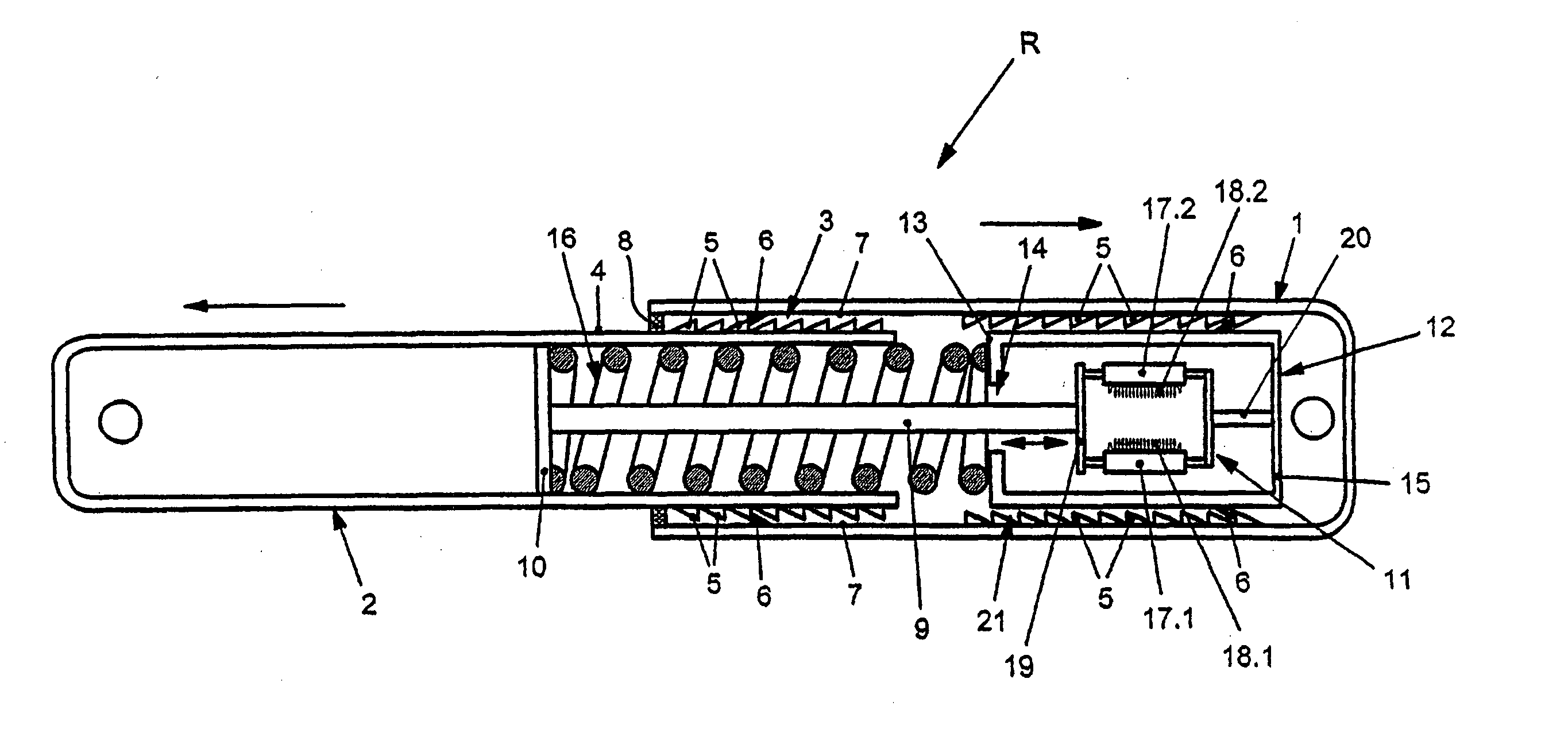
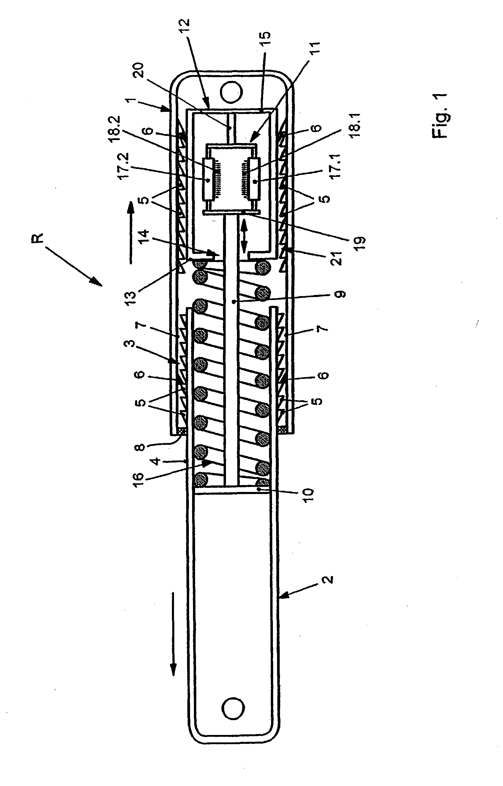
[0016] In FIG. 1, a distraction device R according to the invention has two elements 1, 2 which can be moved relative to one another, the element 2 preferably being able to be pushed as a tube into the element 1. A first detent device 3 has, on an outer surface 4 of the element 2, detent lugs 5 in which at least one catch 6 of the element 1 engages. The catch 6 is preferably assigned to an inner wall 7 of the element 1 or is formed by this.

[0017] The detent device 3 permits a distraction movement of the element 1 and of the element 2 away from one another in the direction of the arrows illustrated, but not a movement in toward one another. In the latter case, the catch 6 engages between the detent lugs 5 and blocks any movement toward one another of element 1 and element 2. Only a distraction, i.e. a movement of element 1 and element 2 away from one another, is guaranteed by the arrangement of the detent device 3.

[0018] A seal 8 seals off the annular gap formed between element 1 a...


PUM


Abstract

A distraction device for moving a one-part or two-part or separated bone apart in order to extend or bridge a bone gap. The device is optionally provided in the form of an intramedullary pin, which can be inserted into a medullary space of a bone and which has at least two elements that can be axially moved in relation to one another. The first element is joined to the second element via at least one detent device for securing a distraction movement, and a pushing module for distracting the first element is assigned to the second element and is joined to the second element in a manner that enables it to be locked.

Description

BACKGROUND OF THE INVENTION [0001] The present invention relates to a distraction device for moving a one-piece or two-piece or separated bone apart in order to extend or bridge a bone gap, optionally in the form of an intramedullary nail which can be inserted into a medullary space of a bone and has at least two elements which can be moved axially in relation to one another, the first element being connected to the second element via at least one detent device for securing a distraction movement. [0002] Distraction devices of this kind are known and commercially available in a wide variety of designs. They are used primarily to ensure that, when a bone has been cut through, suitable distraction takes place in order to improve endogenous formation of new bone substance. A corresponding distraction device is described in EP 0 346 247 B1, for example, in which an intracorporeal bone intramedullary nail is disclosed which moves two parts of a bone by mechanical means. Such a distractio...

Claims


Application Information

Patent Timeline
Patent Type & Authority Applications(United States)
IPC IPC(8): A61B17/00A61B17/66A61B17/72
CPCA61B17/66A61B2017/00867A61B17/7216
Inventor WITTENSTEIN, MANFRED
Owner WITTENSTEIN GROUP
Why Eureka
Try Eureka