Variable force valve spring

a valve spring and variable force technology, applied in the direction of non-mechanical valves, machines/engines, mechanical apparatus, etc., can solve the problems of reducing the overall engine efficiency, contributing to the parasitic loss of the engine, and unable to alter or control the amount of force required to compress the valve spring, etc., to achieve the effect of increasing the spring force of the valve spring

Inactive Publication Date: 2012-08-02
SKADERI GRUP LLC
View PDF4 Cites 6 Cited by
  • Summary
  • Abstract
  • Description
  • Claims
  • Application Information

AI Technical Summary

Benefits of technology

[0049]In another aspect of at least one embodiment of the invention, a method of actuating a valve of an engine is provided that includes increasing a spring force of a valve spring associated with the valve based on an increase in an engine parameter, and decreasing the spring force of the valve spring based on a decrease in the engine parameter.

Problems solved by technology

One problem with this system is that there is no way to alter or control the amount of force required to compress the valve spring.
In conventional internal combustion engines, a stronger valve spring produces higher rocker shaft and cam shaft bearing friction, contributing to the parasitic losses of the engine and reducing overall engine efficiency.
Traditional mechanical valve springs are also poorly suited for “lost-motion” valve train systems.
Since none of the energy is returned to the cam, the energy spent to compress the valve spring in the first place is essentially wasted.

Method used


Image

  • Variable force valve spring
  • Variable force valve spring
  • Variable force valve spring

Examples


Embodiment Construction

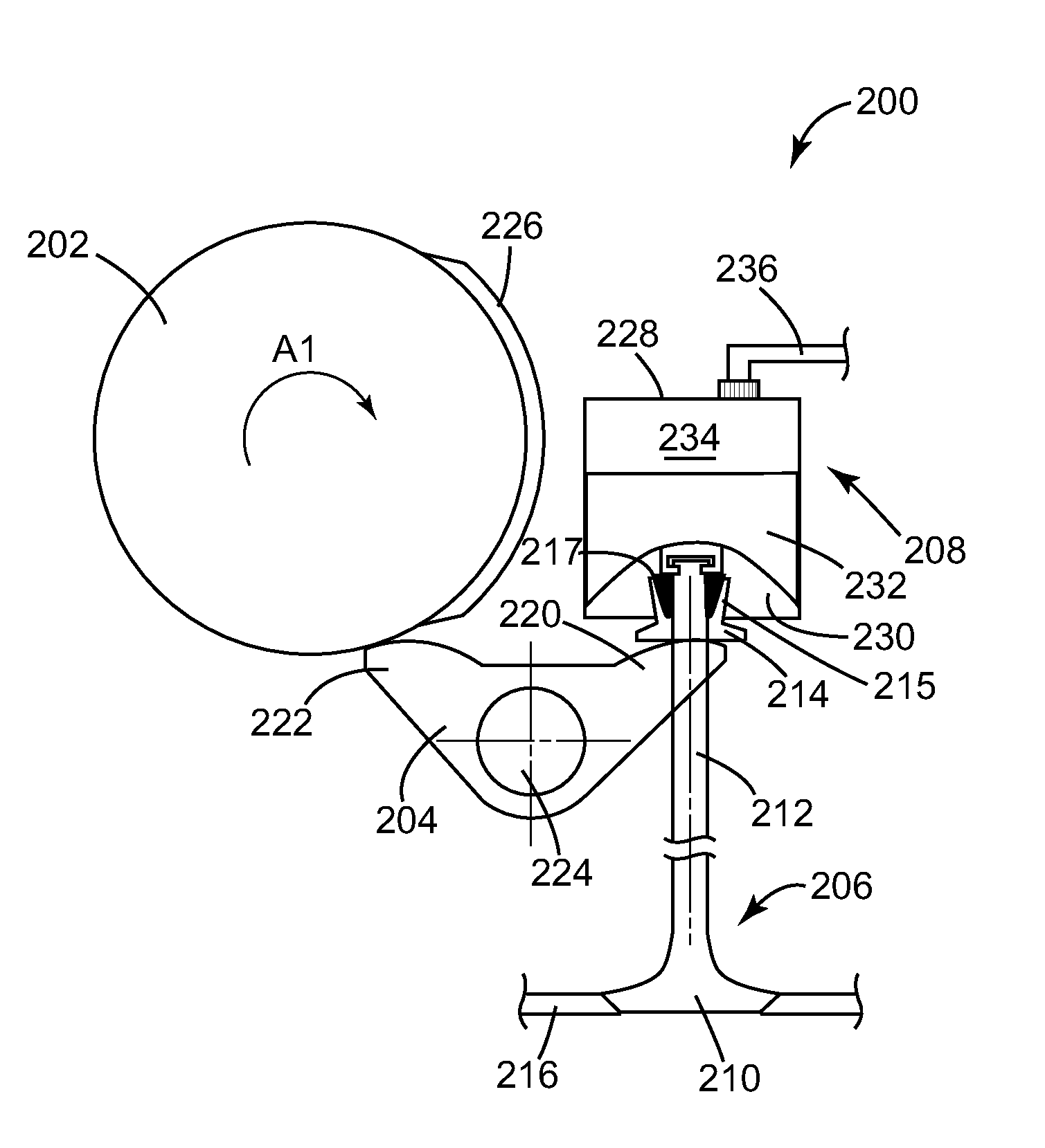
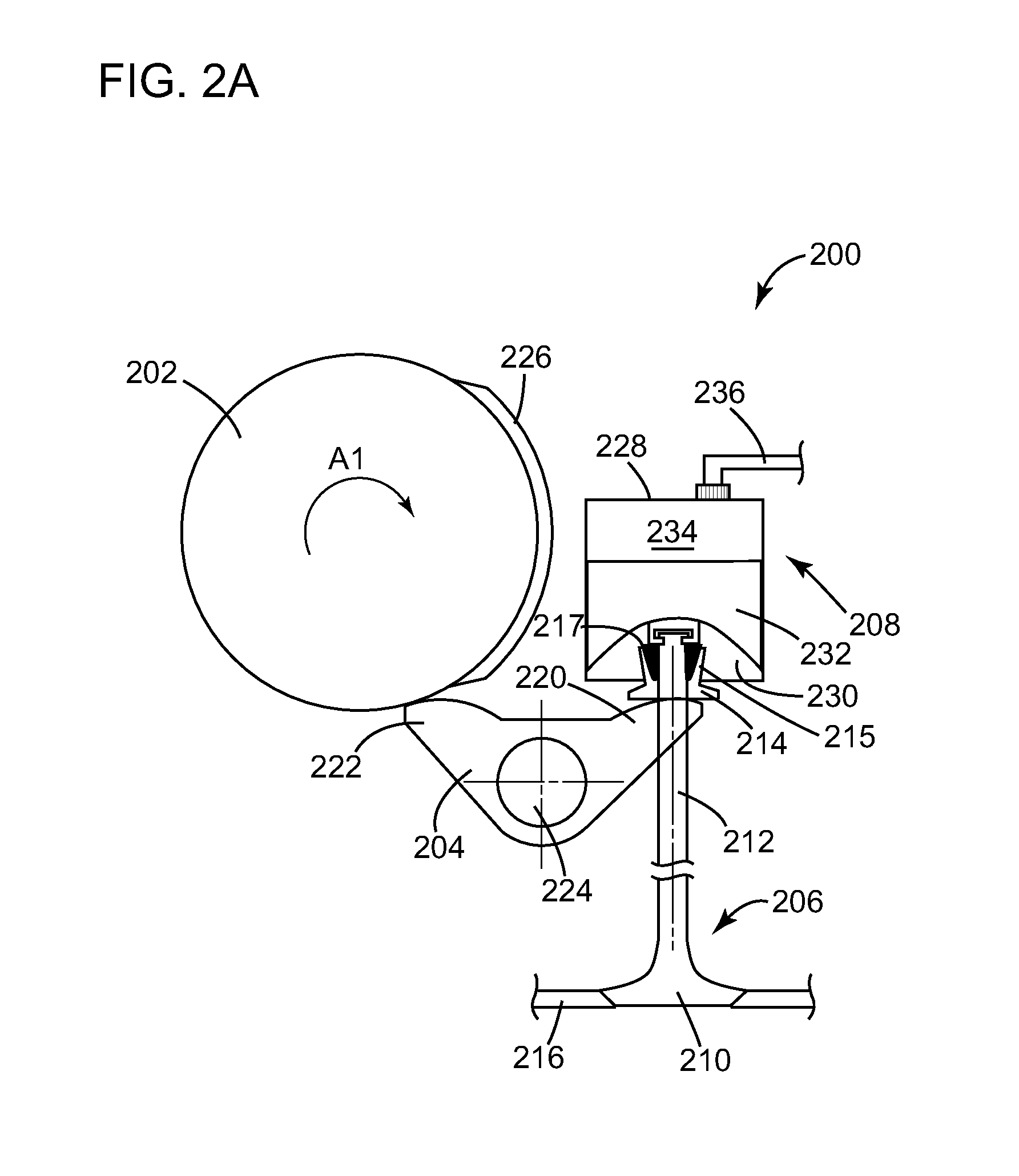
[0068]Certain exemplary embodiments will now be described to provide an overall understanding of the principles of the structure, function, manufacture, and use of the devices and methods disclosed herein. One or more examples of these embodiments are illustrated in the accompanying drawings. Those skilled in the art will understand that the devices and methods specifically described herein and illustrated in the accompanying drawings are non-limiting exemplary embodiments and that the scope of the present invention is defined solely by the claims. The features illustrated or described in connection with one exemplary embodiment may be combined with the features of other embodiments. Such modifications and variations are intended to be included within the scope of the present invention.

[0069]Although certain methods and devices are disclosed herein in the context of a split-cycle engine and / or an air hybrid engine, a person having ordinary skill in the art will appreciate that the m...


PUM

PropertyMeasurementUnit
load thresholdaaaaaaaaaa
pressureaaaaaaaaaa
pressureaaaaaaaaaa

Abstract

Devices and related methods are disclosed that generally involve variable force valve springs for controlling the motion of an engine valve. The force exerted by the valve spring can be adjusted by altering the pressure at which a fluid is supplied to a fluid chamber thereof, by altering the volume of the fluid chamber, and/or by changing the aggregate surface area over which fluid pressure is coupled to the engine valve. Associated fluid control systems are also disclosed herein, as are various methods for adjusting the force of a valve spring based on a variety of engine parameters, such as engine speed, engine load, and/or a combination thereof.

Description

CROSS-REFERENCE TO RELATED APPLICATIONS[0001]This application claims the benefit of priority of U.S. Provisional Patent Application No. 61 / 436,739, filed on Jan. 27, 2011, the entire contents of which are incorporated herein by reference.FIELD[0002]The present invention relates to methods and devices for actuating an engine valve. More particularly, the invention relates to variable force valve springs and methods related thereto.BACKGROUND[0003]Internal combustion engines generally include one or more valves for controlling the flow of air and fuel through the engine. These valves are usually actuated by a mechanical cam. For example, a rotating shaft having a teardrop-shaped cam lobe can be configured to impart motion to the valve, either directly or via one or more intermediate elements. As the shaft rotates, the eccentric portion of the cam lobe imparts a linear motion to the valve over a range of the shaft's rotation.[0004]It is often necessary to bias the valve towards a parti...

Claims


Application Information

Patent Timeline
Patent Type & Authority Applications(United States)
IPC IPC(8): F01L9/00B21K1/76
CPCF01L1/465F01L3/10Y10T29/49247F01L2003/258F02B33/22F01L3/22
Inventor MELDOLESI, RICCARDOSCHWOERER, JOHNPATURZO, JOSEPH
Owner SKADERI GRUP LLC
Why Eureka
Try Eureka