

Loose-leaf binder
A technology of a binder and a fulcrum, applied in the field of binders, can solve problems such as loose pages, problems with manufacturing time or cost, rust, etc., and achieve the effect of solving weight, solving manufacturing time and cost.
- Summary
- Abstract
- Description
- Claims
- Application Information
AI Technical Summary
Problems solved by technology
Method used
Image

Examples
Embodiment 1
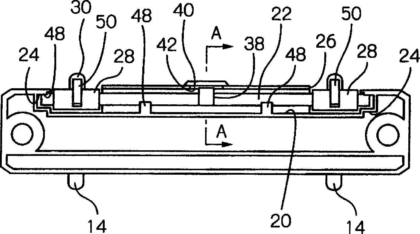
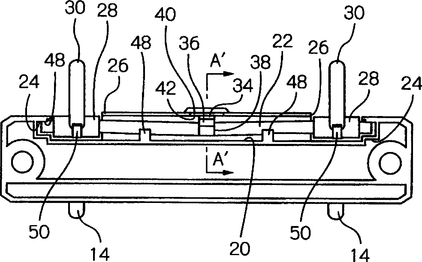
[0085] The fulcrum 22 of the binder of the first embodiment has a triangular cam 38 at an intermediate position in the longitudinal direction, and the triangular cam 38 has a front cam 34 and a rear cam 36 ( When the movable ring 30 is opened, the former is "front", and the latter is "rear"). On the other hand, the base body 16 has a front cam 34 and a rear cam 36 that are arranged at different rotational positions when the fulcrum 22 is rotated. The first locking portion 40 and the second locking portion 42 that are in contact.
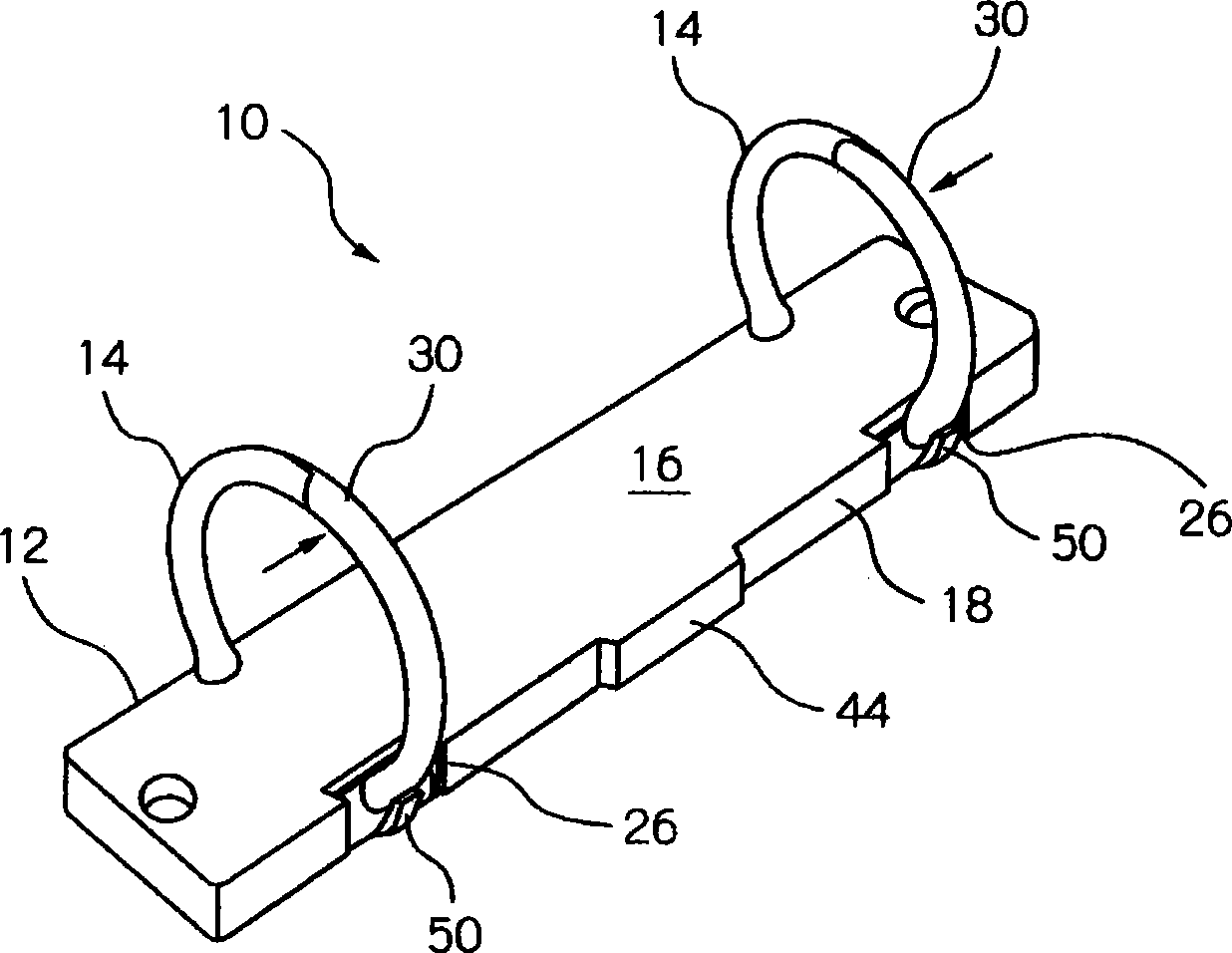
[0086] The front cam 34 and the rear cam 36 are provided at an intermediate position in the longitudinal direction of the support shaft 22, and the first locking portion 40 and the second locking portion 42 are formed on the second side edge portion 18 of the base body 16, for example figure 1 The inner side of the protruding side wall portion 44 as shown is formed in the inner segment of the side wall portion 44 to constitute the first locking port...
Embodiment 2
[0094] Figure 8 to Figure 11 The second embodiment of the present invention is illustrated. In the second embodiment, the front cam 134 and the rear cam 136 are formed in the opposite direction of the support shaft 22 from the first embodiment. In addition, the first locking portion 140 and the second locking portion 142 are constituted by the second side edge portion 18 of the base body 16 and the reinforcing rib 46 located inward of the support shaft 22 . The inner stage portion viewed from the side constitutes the first locking portion 140 , and the inner surface portion that can extend from the edge end of the inner stage portion of the reinforcing rib 46 constitutes the second locking portion 142 .
[0095] Similar to the first embodiment, when the movable ring 30 and the fixed ring 14 are engaged with each other, the front cam 134 is Figure 8 The shown position before closing is in contact with the first locking portion 140 . From this state, the movable ring 30 is ...
Embodiment 3
[0105] Below, refer to Figure 13 to Figure 22 A third embodiment of the present invention will be described.
[0106] Figure 13 The third embodiment of the binder according to the present invention is indicated by reference numeral 100. The binder 100, like the binders of the first and second embodiments, has a plate-like base 16 with two fixing rings 14 fixed along the first side edge 12 thereof, and a third plate along the base. The two side edge portions 18 are arranged in a pivot support groove 20 provided in the base, and a pivot 22 which can be bent and twisted freely.
[0107] The support shaft 22 of the binder 100 according to the third embodiment includes a rear cam 102 extending in the radial direction at an intermediate position in the longitudinal direction, and the rear cam 102 is positioned on each side of the rear cam 102 close to the major diameter portions 28, And the front cam 104 which differs from the rear cam 102 in the circumferential direction posit...
PUM
 Abstract
Description
Claims
Application Information