Loose-leaf binder

A technology of binders and fulcrums, applied in the field of binders, which can solve the problems of scattered binders, manufacturing time or cost, inability to provide spring force, etc., and achieve the effect of solving weight, manufacturing time and cost

Active Publication Date: 2011-04-20
金田克已
View PDF3 Cites 0 Cited by
  • Summary
  • Abstract
  • Description
  • Claims
  • Application Information

AI Technical Summary

Problems solved by technology

[0004] However, in the binder of this structure, in addition to preparing spring members with different sizes and spring forces or lengths for the binder, a more complicated structural part must be carefully designed so that on the shaft member and the base material, Assembling the above-mentioned spring member without detaching from the base material and without impairing the effective spring action, there is a problem in terms of manufacturing time or cost, and there is also a problem that a metallic shaft is used in order to improve the durability of the coil spring-related members. component, which can cause weight gain or rust
In addition, it takes labor and time to sort metal springs when they are discarded
In addition, especially the technology of the above-mentioned Japanese Patent No. 3749893 has the following problem. If the ring is opened, the semi-rings will be opened suddenly, causing the bound loose-leaf to be scattered.
[0005] On the one hand, although as explained in Japanese Patent No. 3407672 (Patent Document 2), especially paragraph (0024), the following binder is proposed, which is provided with a low protrusion on the outer periphery of the shaft body, and the bearing A concave-convex sliding joint corresponding to the low protrusion is formed on the inner periphery of the part. Through the contact action between the low protrusion and the sliding joint, the rotation of the shaft body has a moderate sense, but the low protrusion is only used to make the shaft body Although it is described that paper can be taken out or put in at a predetermined position (paragraph 0032), it does not have sufficient braking force to stop at a predetermined position, and cannot provide a substitute for promoting ring opening. previous spring force for closing action

Method used


Image

  • Loose-leaf binder
  • Loose-leaf binder
  • Loose-leaf binder

Examples


Embodiment 1

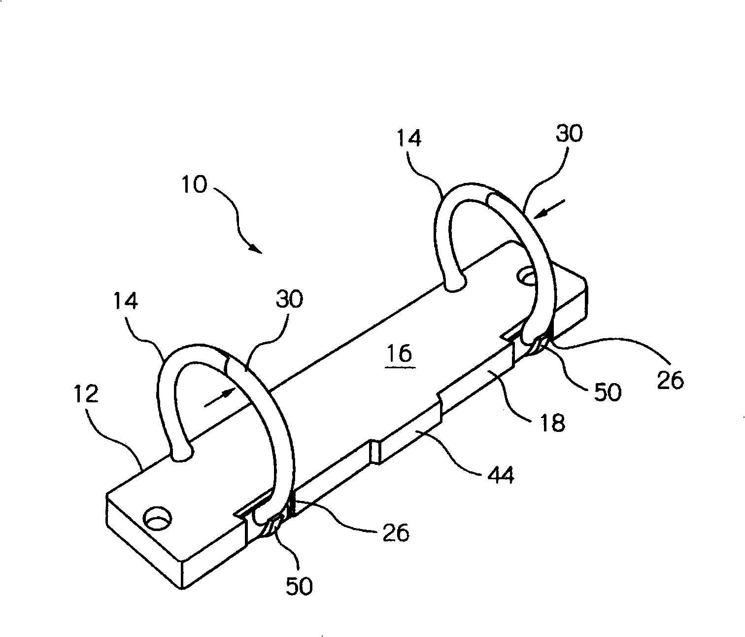
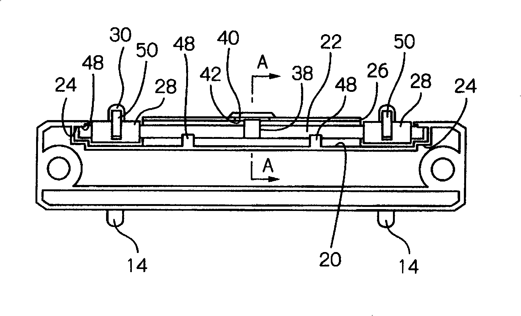
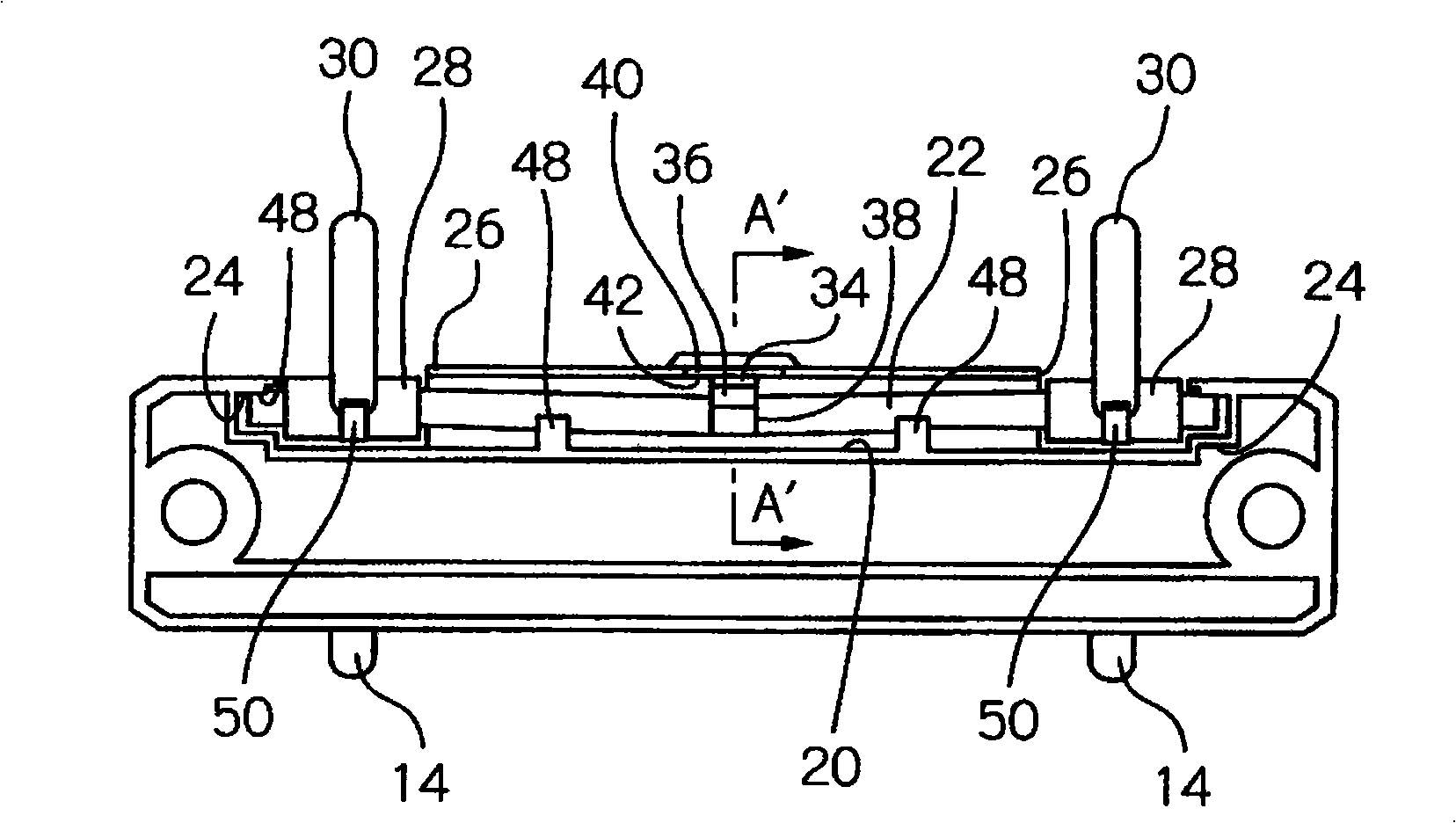
[0085] The supporting shaft 22 of the binder of the first embodiment has a triangular cam 38 at the middle position in the longitudinal direction. The triangular cam 38 has a front cam 34 and a rear cam 36 ( When the movable ring 30 is opened, the former is "front", and the latter is "rear"). On the other hand, the base body 16 has a configuration such that the front cam 34 and the rear cam 36 are at different rotational positions when the fulcrum 22 rotates. The first locking part 40 and the second locking part 42 that are in contact.

[0086] The front cam 34 and the rear cam 36 are arranged at the middle position in the longitudinal direction of the support shaft 22, and the first locking part 40 and the second locking part 42 are formed on the second side edge part 18 of the base body 16, for example figure 1 The inner side of the protruding side wall portion 44 is formed on the inner side portion of the side wall portion 44 to form the first locking portion 40, and the i...

Embodiment 2

[0094] Figure 8 ~ Figure 11 The second embodiment of the present invention is illustrated. In the second embodiment, the front cam 134 and the rear cam 136 are formed in the direction opposite to that of the first embodiment of the spindle 22 . In addition, the first locking part 140 and the second locking part 142 are constituted by the second side edge part 18 of the base body 16 and the reinforcing rib 46 which is closer to the inner side than the support shaft 22, and the groove formed in the reinforcing rib 46 The inner segment viewed from the side constitutes the first locking portion 140 , and the inner surface portion of the reinforcing rib 46 that can extend from the edge of the inner segment constitutes the second locking portion 142 .

[0095] As in the first embodiment, when the movable ring 30 and the fixed ring 14 are engaged with each other, the front cam 134 is Figure 8 The shown pre-closing position is in contact with the first locking portion 140 . From ...

Embodiment 3

[0105] Below, refer to Figure 13 ~ Figure 22 A third embodiment of the present invention will be described.

[0106] Figure 13 The whole of the third embodiment of the binder of the present invention is denoted by numeral 100. The binder 100 is the same as the binders of the first embodiment and the second embodiment, and has a plate-shaped base 16 fixedly provided with two fixing rings 14 along its first side edge 12, and a second base 16 along the base. 2 The side edge portion 18 is disposed in a support shaft support groove 20 provided in the base, and a support shaft 22 that is freely bendable and freely twistable.

[0107] The supporting shaft 22 of the binder 100 of the third embodiment has: a rear cam 102 extending radially at the middle position in the longitudinal direction thereof, and positioned on each side of the rear cam 102 and close to each diameter portion 28 , And the front cam 104 which differs from the rear cam 102 in the circumferential position of th...


PUM


Abstract

The invention provides a binder integrally made of plastic, performing opening action divided into two stages in rotor ring and preventing the binder from being fallen off, as well as providing a narrow first opening state capable of inserting few binders and wider second opening state capable of inserting a plurality of binders.

Description

technical field [0001] The invention relates to a binder. Background technique [0002] Conventionally, there are a large number of binders in which a plurality of fixing rings are provided on one side of an elongated plastic substrate, and a ring supported by a shaft member is arranged on the other side. A plurality of movable rings are rotatable and can be freely opened and closed by locking with a fixed ring. Loose-leaf papers provided with insertion holes corresponding to the rings are detachably stapled to such rings. [0003] Such prior binders include the following binders, etc., as described in Japanese Patent No. 3749893 (Patent Document 1), attached to this specification Figure 24 as well as Figure 25 As shown in the number 400, the shaft member is packed into a metal coil spring 408, so that when the movable second half-ring element 402 with a hook-shaped engaging means 405 is twisted with a finger, the first half-ring element 402 can be moved from the fixed fi...

Claims


Application Information

Patent Timeline
Patent Type & Authority Patents(China)
IPC IPC(8): B42F3/04B42F13/22
CPCB42F3/04B42F13/22
Inventor 金田浩士
Owner 金田克已
Why Eureka
Try Eureka