
Method for effecting a screwed connection

a screw and connection technology, applied in the direction of screws, nuts, measurement/indication equipment, etc., can solve the problems of fatigue occurring too early, complex manufacture complex manufacturing of threaded bolts and washers, etc., to achieve simple configuration, simple design, and precise measurement of screw clamping force

Active Publication Date: 2011-10-11
HOHMANN JORG +1
View PDF14 Cites 6 Cited by
  • Summary
  • Abstract
  • Description
  • Claims
  • Application Information

AI Technical Summary

Benefits of technology

[0009]The invention has the object to provide a screwed connection that is of a simple configuration, requires only a screwing tool of a simple design, and enables a precise measurement of the screw clamping force.
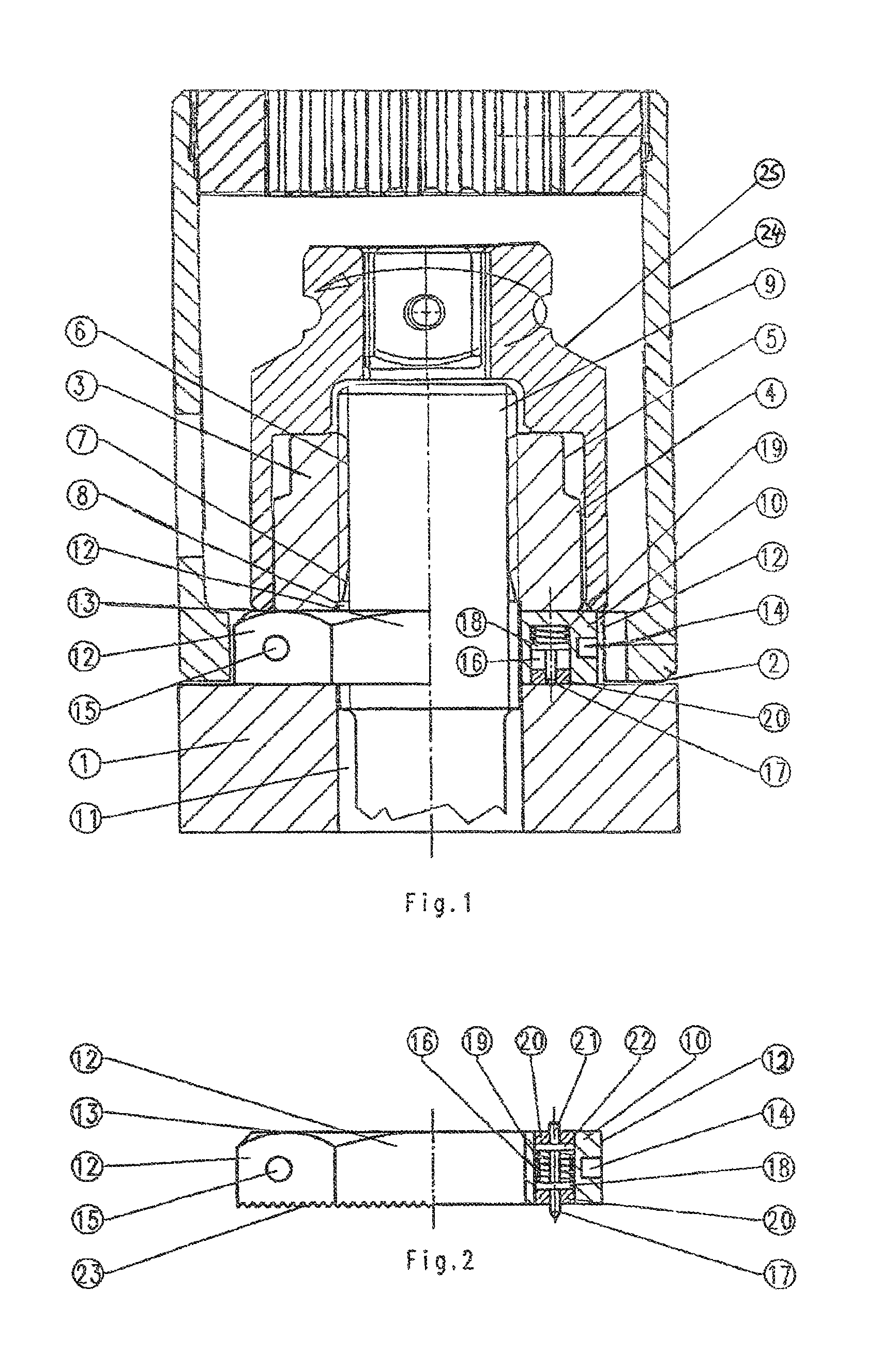
[0012]The outer periphery of the washer is of a polygon shape and has, in particular, a hexagon shape, the measuring element can be arranged so as to be recessed within one of the flat surfaces so that in this way it is protected from being damaged by the holding tool.
[0018]The spring force acting on the pin or the annular segments can advantageously be increased when tightening the nut by means of at least one moveable pressure element that interacts with the nut and projects past the surface of the washer that is facing the nut.

Problems solved by technology

The frictional anti-rotation action of the washer relative to the threaded bolt according to EP 1 435 279 A1 can cause damage on the thread of the threaded bolt and thus lead to fatigue occurring too early.
Moreover, the washer is designed in a special way so that its manufacture is complex.
In this way, the manufacture of the threaded bolt and of the washer is more complex and the fatigue strength of the threaded bolt may be impaired.
The screw clamping force is determined in these known screwed connections by measuring the torque applied to the nut but this measurement is extremely imprecise because the frictional conditions in the screwed connection can fluctuate within a wide range as is well known in the art.

Method used


Image

  • Method for effecting a screwed connection
  • Method for effecting a screwed connection

Examples


Embodiment Construction

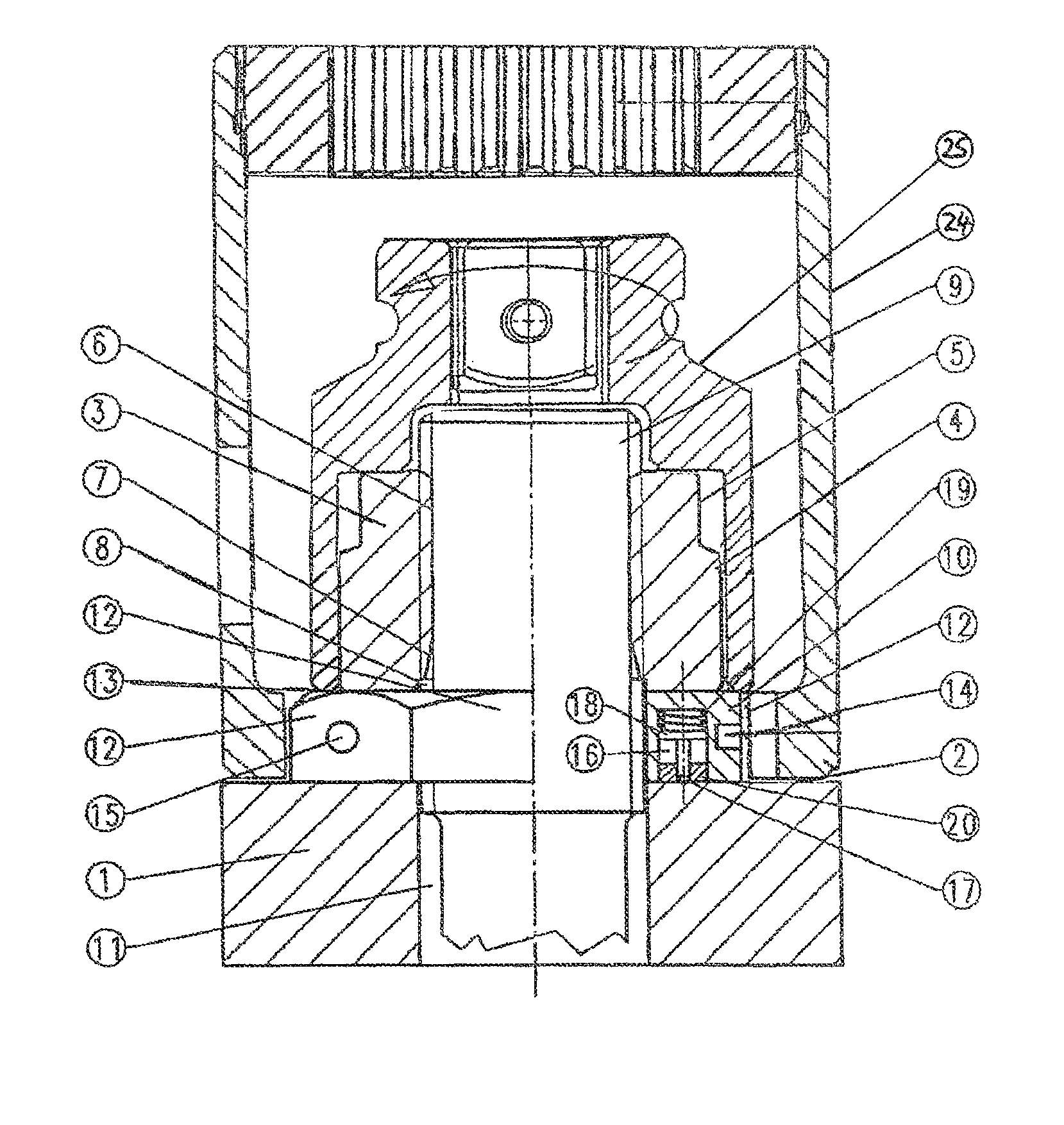
[0024]The component 1 to be clamped is schematically shown only a bore 11 for receiving a threaded bolt 9 and by a surface 2 against which the washer 10 is resting.

[0025]Onto the threaded end of the threaded bolt 9 a nut 3 is screwed that, in the illustrated embodiment, has a cylindrical area 4 and an area 5 with a configuration for positive-locking engagement of a nut-tightening tool 25. The nut 3 is screwed onto the threaded end 6 of the threaded bolt 9 and has on the end that is facing the washer 10 a conical recess 7 as well as a recess 8 that leaves off at least one turn of the thread, which recesses serve for distributing the force transmission onto several thread turns.

[0026]The washer 10 is also provided with configurations for positive locking engagement of a holding tool 24; in the illustrated embodiment flat surfaces 12 of an external hexagon are provided. Recessed in the area of a flat surface 12 there is a measuring element 14 by means of which the compressive force cau...


PUM

PropertyMeasurementUnit
Forceaaaaaaaaaa
Electrical inductanceaaaaaaaaaa
Capacitanceaaaaaaaaaa

Abstract

A screwed connection has a threaded bolt; a nut; a washer arranged between the nut and a surface of a component to be clamped; a screwing device with a housing, a holding tool connected to the housing, and a tightening tool that engages positively the nut; a measuring element arranged in the washer for measuring a compressive force generated by tightening the screwed connection. The washer has an anti-rotation device oriented toward the surface of the component. The outer periphery of the washer is positive-lockingly engaged by the holding tool. The washer has no positive or frictional connection to the threaded bolt, and the holding tool has no torque supporting action on the threaded bolt or on any other part so that a reaction moment, generated when tightening the nut, is introduced from the housing of the screwing device through the washer into the component to be clamped.

Description

BACKGROUND OF THE INVENTION[0001]The invention concerns a screwed connection comprised of a threaded bolt, a nut, and a washer positioned between the nut and a surface of a component to be clamped.[0002]Such screwed connections wherein the washer is engaged by a holding tool and the nut by a tightening tool are disclosed in EP 0 988 935 A2, EP 1 080 847 A2, and EP 1 435 279 A1.[0003]According to EP 0 988 935 A2 a positive locking connection between the threaded bolt and the washer exists while according to EP 1 435 279 A1 a friction connection between the threaded bolt and the washer is provided. Additionally, according to EP 0 988 935 A2 a further holding element connected to the first holding element can positively engage the threaded bolt. In contrast to this, in the screwed connection according to EP 1 080 847 A2 there is no connection between the threaded bolt and the washer but holding tools that are connected to one another engage the washer as well as the threaded bolt in a ...

Claims


Application Information

Patent Timeline
IPC IPC(8): B21D39/00
CPCF16B31/028G01L5/243Y10T29/49947Y10T29/49764Y10T29/49963Y10T29/49771Y10T29/49948
Inventor HOHMANN, JORGHOHMANN, FRANK
Owner HOHMANN JORG
Learn More