[0011] In one aspect of the present invention, a prosthetic disc for
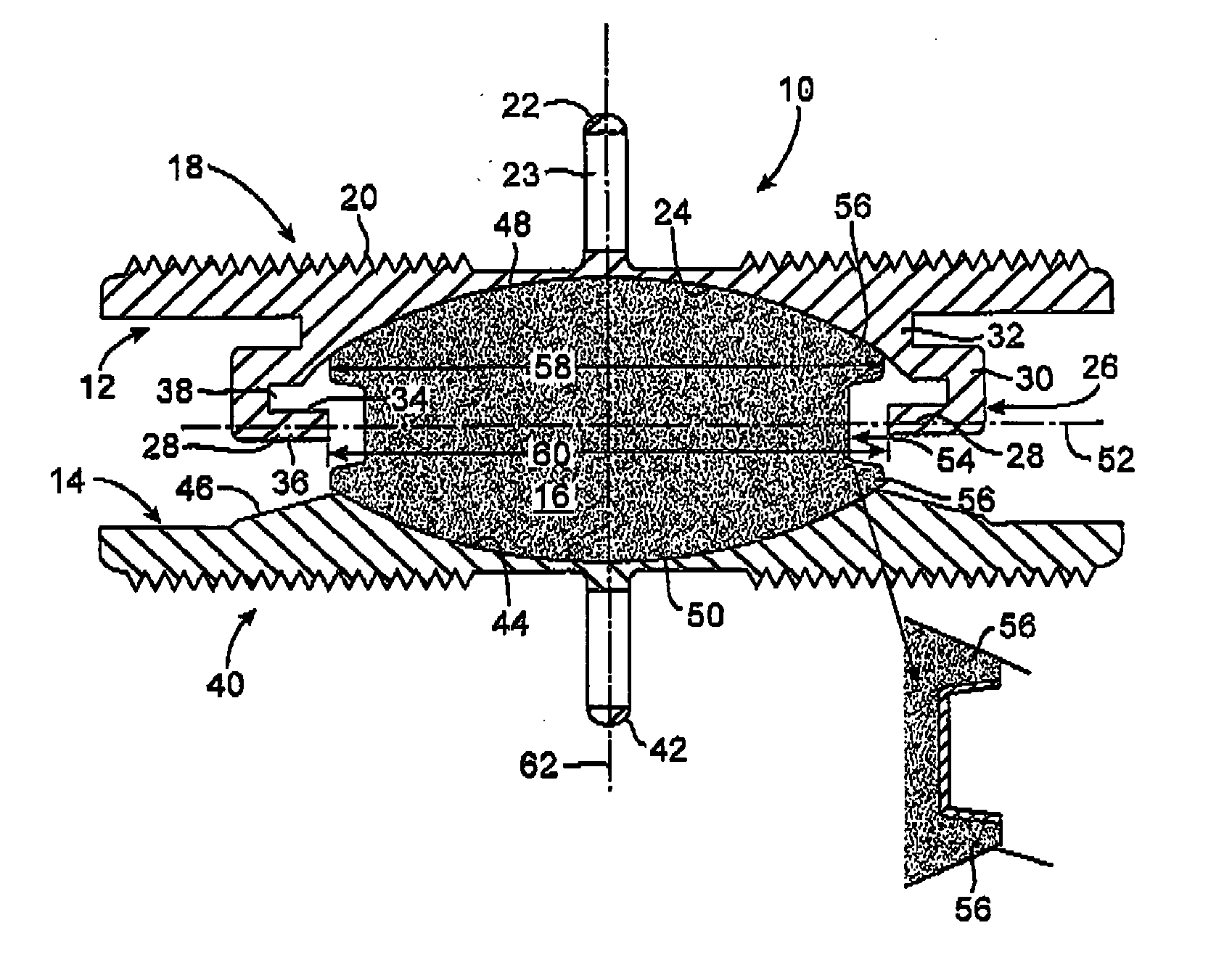
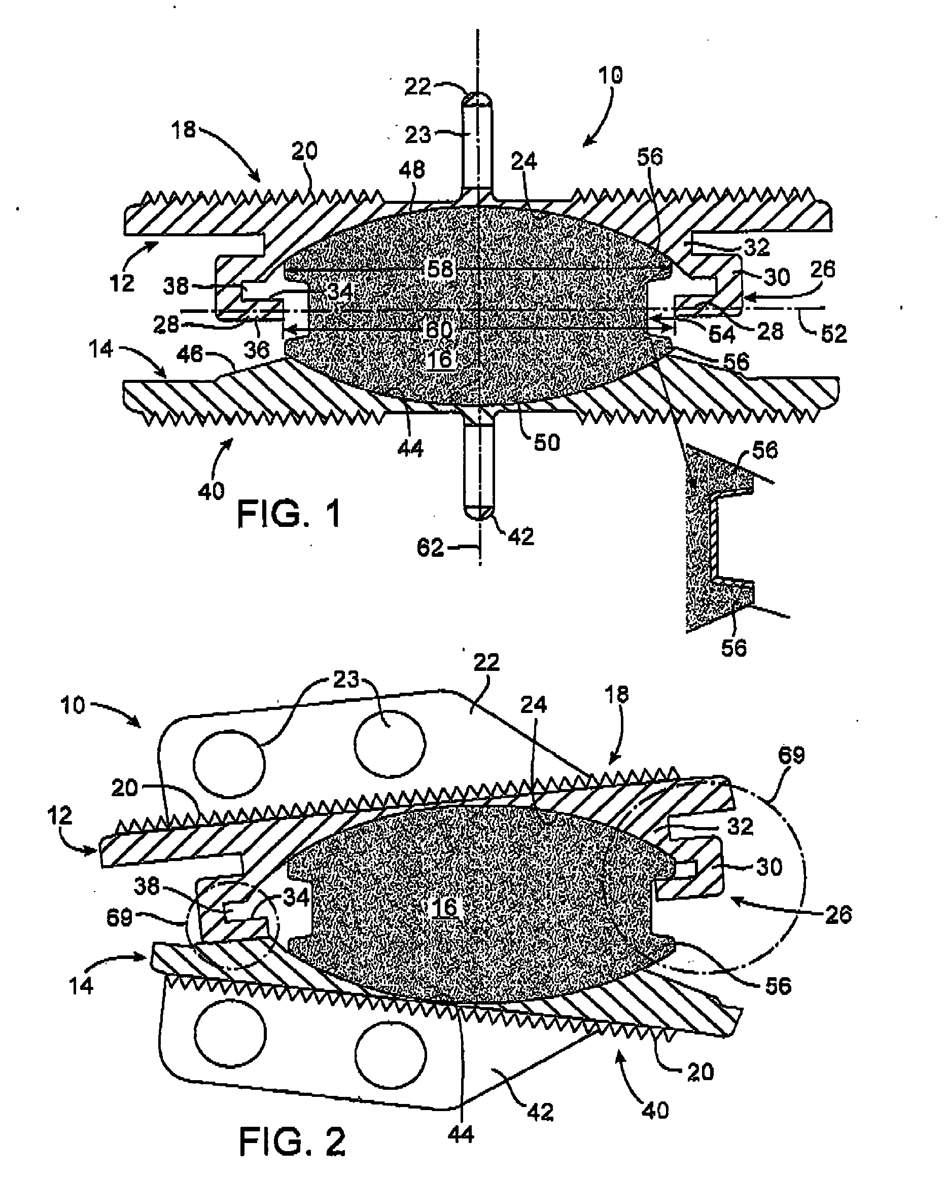
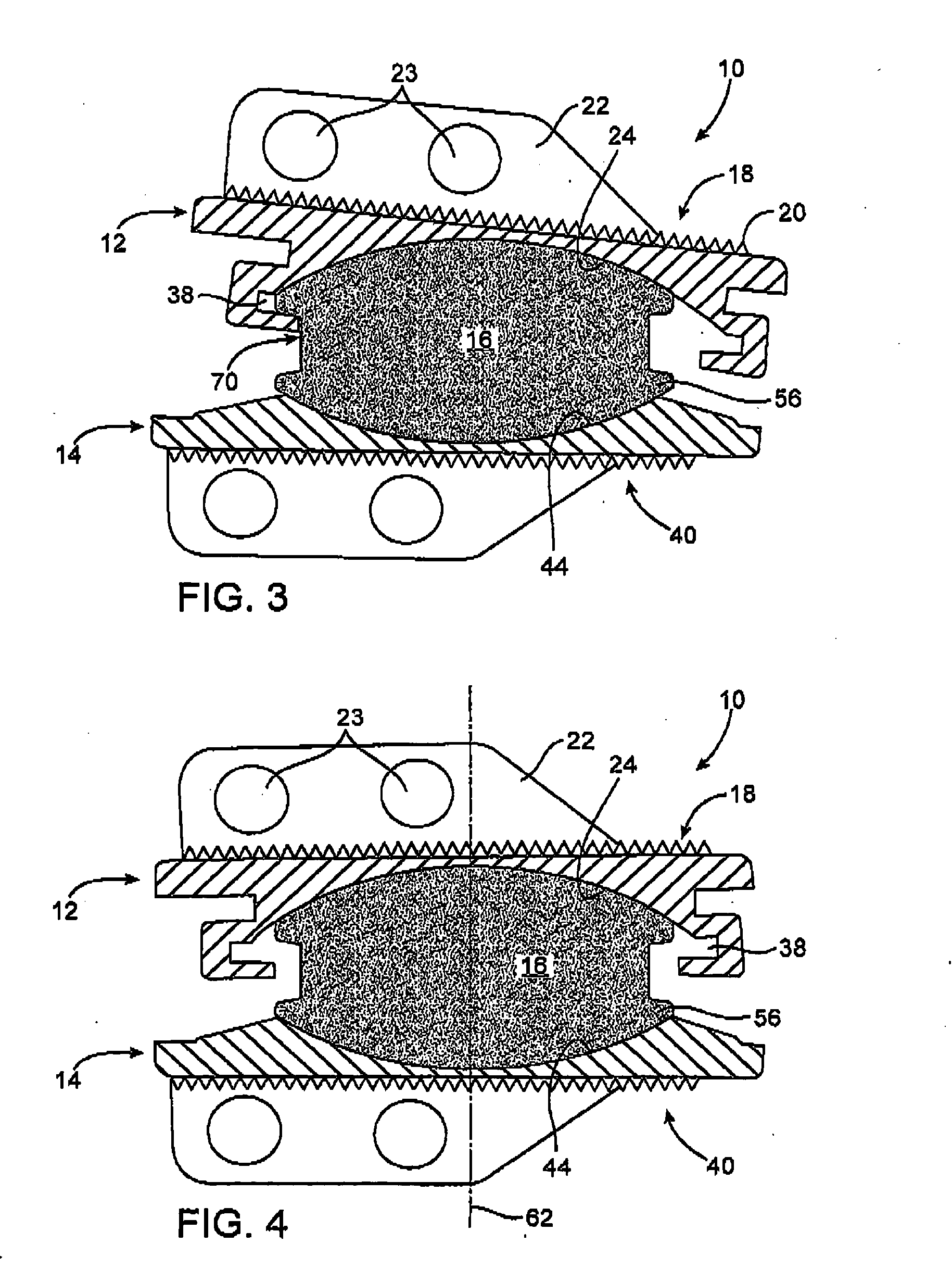
insertion between adjacent vertebrae includes upper and lower plates having outer surfaces, which engage and are locatable against the respective vertebrae, and inner curved surfaces. A core is disposed between the curved surfaces to allow the plates to slide over the core. Preferably, the plates can slide freely in all directions, not being limited to movement in a single direction as with the prior art. The present invention further provides peripheral restraining structure on one or both of the plates or the core to hold the core against the curved surface of at least one of the plates during sliding movement of the plates over the core. The peripheral restraining structure defines a limit or boundary for movement of the core relative to at least one of the upper and lower plates. Within such a peripheral boundary, however, movement of the core relative to the plate will preferably be unconstrained. That is, movement of the core relative to the plate may occur in any direction without significant inhibition or friction. The core will preferably not be attached to either the upper or lower plate, and the plates will thus be able to freely articulate relative to each other over the core, which provides a
low friction bearing surface.
[0012] An
advantage of the structure thus described is that the surface contact area between the core and each of the upper and lower plates may be maximized. By providing only a peripheral restraint, as opposed for example to grooves and keys on the surface of the core and plates, the width or
diameter of the core relative to the size of the plate may be maximized. Moreover, the surfaces of the core and the plates which contact each other may be made smooth and free from other structure(s) that might adversely affect performance. In the preferred embodiments, both the curved surfaces of the plates and the corresponding surfaces of the core will be spherical sections. The use of spherical surfaces promotes free, unconstrained
relative motion of the plates and the core in all directions.
[0013] In some embodiments, the peripheral restraining structure limits relative inclination of the plates during sliding movement of the plates over the core, usually by defining a stop structure. In other embodiments, the peripheral restraining structure lifts one side of the core relative to an opposite side of the core during sliding movement of the plates over the core. The peripheral restraining structure itself may take any of a number of different forms. In one embodiment, for example, the restraining structure comprises a ring structure on at least one of the upper and lower plates and an annular structure on at least a portion of the periphery of the core. The ring structure will be adapted to engage and restrain the annular structure on the core. For example, the ring structure may comprise a
flange which defines an overhang over at least a portion of the periphery of one of the plates. The overhang of the
flange will receive the annular structure on the core to provide an
interference fit which retains the core against the curved surface of the plate but allows the core to slide freely and in an unconstrained manner within the limit or boundary defined by the
flange. The annular structure on the core may be a rim which extends continuously or discontinuously (preferably continuously) around a lateral circumference of the core. By providing a rim which has a width, usually a
diameter, which is slightly greater than the corresponding width of an inner edge of the flange at one point, the core will be held in place and will not be dislodged from the cavity defined by the ring structure in normal use.
[0015] The upper and lower plates may be made of any suitable material or combination of materials, such as but not limited to
cobalt chrome
molybdenum and
titanium. In some embodiments,
titanium plates are used, and these plates may optionally include inner surfaces of
titanium nitride and outer surfaces that are aluminum
oxide blasted to create micro-concavities. In another embodiment,
cobalt chrome plates are used, with the outer surfaces being blasted with aluminum
oxide and then coated with a titanium
plasma spray. In some embodiments, the plates comprise an MRI-compatible material, such as titanium, coupled with a hardened material, such as
cobalt chrome
molybdenum. Such materials may be coupled using any suitable means, such as laminating, slip fitting, interferences fitting, adhesion,
welding, molding or the like. Some plates include a
coating or material on the inner surfaces for reducing friction and / or
wear and tear, such as a
titanium nitride surface.

