Sample tube

a technology of sample tube and sample tube, which is applied in the direction of instruments, process and machine control, laboratory glassware, etc., can solve the problems of exact same temperature cycle, error in sample temperature, and lengthen the total time needed to complete the amplification, so as to reduce the reagent cost and reduce the cycle time

Inactive Publication Date: 2005-04-21
APPLERA
View PDF4 Cites 29 Cited by
  • Summary
  • Abstract
  • Description
  • Claims
  • Application Information

AI Technical Summary

Benefits of technology

[0022] According to the teachings of the invention, there is disclosed herein a thin walled sample tube for decreasing the delay between changes in sample temperature of the sample block and corresponding changes in temperature of the reaction mixture. Two different sample tube sizes are disclosed, but each has a thin walled conical section that fits into a matching conical recess in the sample block. Typically, cones with 17° angles relative to the longitudinal axis are used to prevent jamming of the tubes into the sample block but to allow snug fit. Other shapes and angles would also suffice for purposes of practicing the invention.
[0029] The teachings of the invention also contemplate a novel design for a disposable plastic 96-well microtiter plate for accommodation of up to 96 individual sample tubes containing DNA for thermal cycling each sample tube having individual freedom of movement sufficient to find the best fit with the sample block under downward pressure from a heated cover. The microtiter plate design, by allowing each tube to find the best fit, provides high and uniform thermal conductance from the sample block to each sample tube even if differing rates of thermal expansion and contraction between the metal of the block and the plastic of the sample tube and microtiter plate structure cause the relative center-to-center dimensions of the wells in the sample block to change relative to the center-to-center distance of the sample tubes in the disposable microtiter plate structure.
[0030] The teachings of the invention also contemplate a novel method and apparatus for controlling the PCR instrument which includes the ability to continuously calculate and display the temperature of the samples being processed without directly measuring these temperatures. These calculated temperatures are used to control the time that the samples are held within the given temperature tolerance band for each target temperature of incubation. The control system also controls a three-zone heater thermally coupled to the sample block and gates fluid flow through directionally interlaced ramp cooling channels in the sample block which, when combined with a constant bias cooling flow of coolant through the sample block provides a facility to achieve rapid temperature changes to and precise temperature control at target temperatures specified by the user. The method and apparatus for controlling the three-zone heater includes an apparatus for taking into account, among other things, the line voltage, block temperature, coolant temperature and ambient temperature in calculating the amount of electrical energy to be supplied to the various zones of the three-zone heater. This heater has zones which are separately controllable under the edges or “guard bands” of the sample block so that excess heat losses to the ambient through peripheral equipment attached to the edges of the sample block can be compensated. This helps prevent thermal gradients from forming.
[0031] The teachings of the invention also contemplate a novel method and apparatus for preventing loss of solvent from the reaction mixtures when the samples are being incubated at temperatures near their boiling point. A heated platen covers the tops of the sample tubes and is in contact with an individual cap which provides a gas-tight seal for each sample tube. The heat from the platen heats the upper parts of each sample tube and the cap to a temperature above the condensation point such that no condensation and refluxing occurs within any sample tube. Condensation represents a relatively large heat transfer since an amount of heat equal to the heat of vaporization is given up when water vapor condenses. This could cause large temperature variations from sample to sample if the condensation does not occur uniformly. The heated platen prevents any condensation from occurring in any sample tube thereby minimizing this source of potential temperature errors. The use of the heated platen also reduces reagent consumption.
[0034] The PCR instrument described herein reduces cycle times by a factor of 2 or more and lowers reagent cost by accommodating PCR volumes down to 20 ul but remains compatible with the industry standard 0.5 ml microcentrifuge tube.

Problems solved by technology

Since the number of cycles is fairly large, this additional time unnecessarily lengthens the total time needed to complete the amplification.
However, in these prior art instruments not all samples experienced exactly the same temperature cycle.
In these prior art PCR instruments, errors in sample temperature were generated by nonuniformity of temperature from place to place within the metal sample block, i.e., temperature gradients existed within the metal of the block thereby causing some samples to have different temperatures than other samples at particular times in the cycle.
Further, there were delays in transferring heat from the sample block to the sample, but the delays were not the same for all samples.
The problems of minimizing time delays for heat transfer to and from the sample liquid and minimizing temperature errors due to temperature gradients or nonuniformity in temperature at various points on the metal block become particularly acute when the size of the region containing samples becomes large.
This large area block creates multiple challenging engineering problems for the design of a PCR instrument which is capable of heating and cooling such a block very rapidly in a temperature range generally from 0 to 100° C. with very little tolerance for temperature variations between samples.
First, the large thermal mass of the block makes it difficult to move the block temperature up and down in the operating range with great rapidity.
Second, the need to attach the block to various external devices such as manifolds for supply and withdrawal of cooling liquid, block support attachment points, and associated other peripheral equipment creates the potential for temperature gradients to exist across the block which exceed tolerable limits.
There are also numerous other conflicts between the requirements in the design of a thermal cycling system for automated performance of the.
However, it is seemingly impossible to add or remove large amounts of heat rapidly in a metal block by these means without causing large differences in temperature from place to place in the block thereby forming temperature gradients which can result in nonuniformity of temperature among the samples.
This makes it increasingly difficult to cycle the temperature of the sample block rapidly while maintaining accurate temperature uniformity among all the samples.
It is difficult to join metal parts in a way that insures uniformly high thermal conductance everywhere across the joint.
Nonuniformities of thermal conductance will generate unwanted temperature gradients.

Method used


Image

  • Sample tube
  • Sample tube
  • Sample tube

Examples


Embodiment Construction

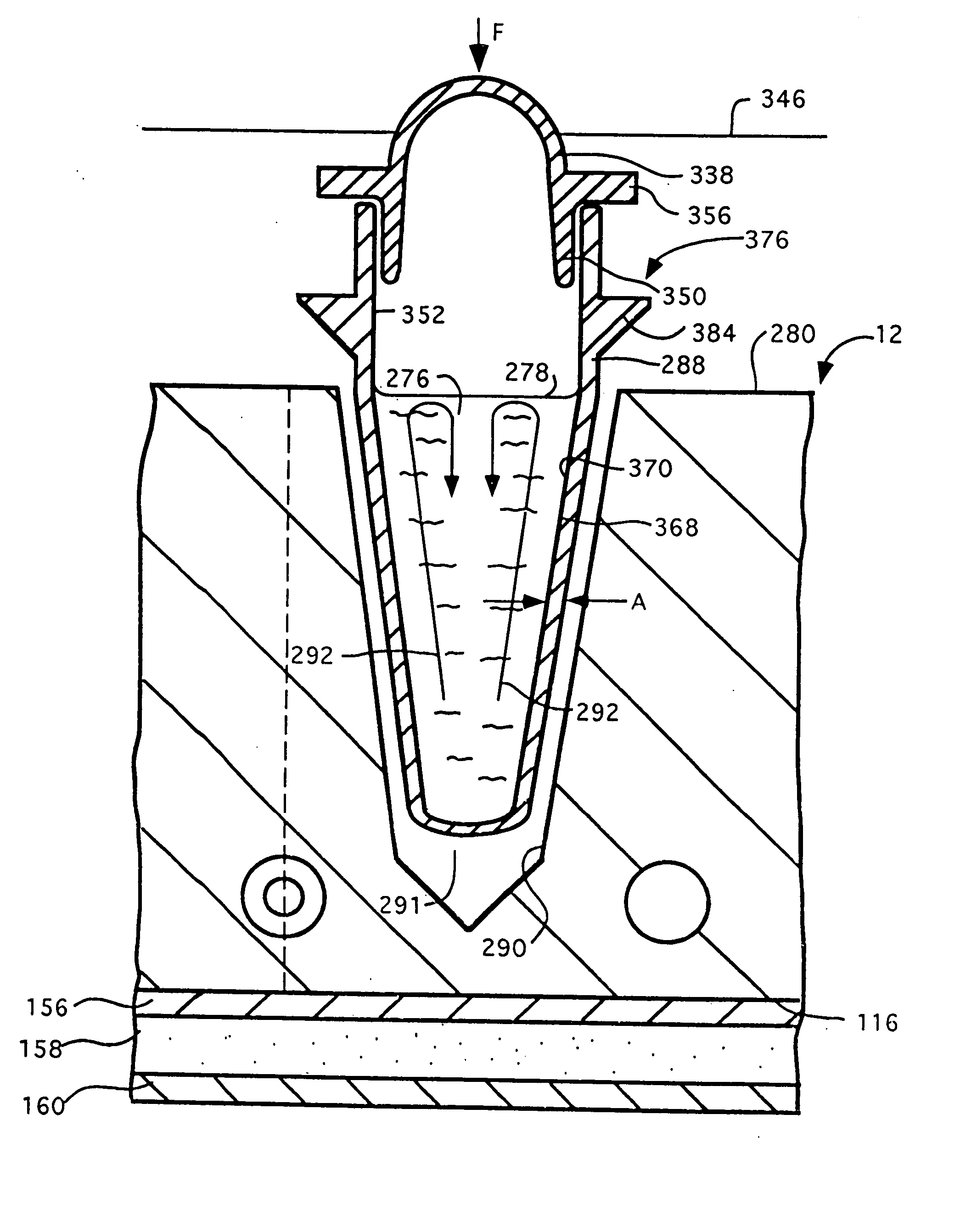
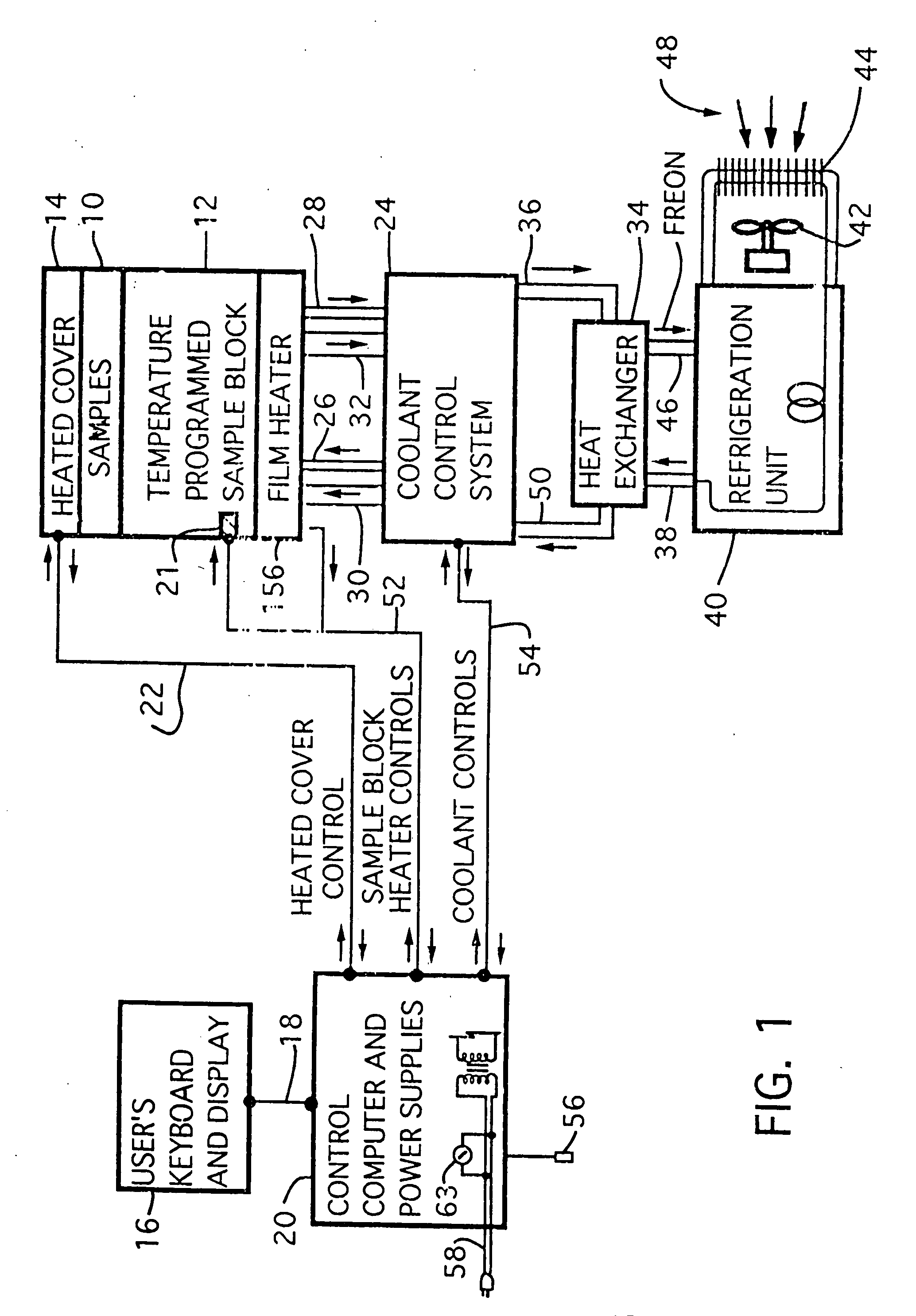
[0096] Referring to FIG. 1 there is shown a block diagram of the major system components of one embodiment of a computer directed instrument for performing PCR according to the teachings of the invention. Sample mixtures including the DNA or RNA to be amplified are placed in the temperature-programmed sample block 12 and are covered by heated cover 14.

[0097] A user supplies data defining time and temperature parameters of the desired PCR protocol via a terminal 16 including a keyboard and display. The keyboard and display are coupled via bus 18 to a control computer 20 (hereafter sometimes referred to as a central processing unit or CPU). This central processing unit 20 includes memory which stores the control program described below, the data defining the desired PCR protocol and certain calibration constants described below. The control program causes the CPU 20 to control temperature cycling of the sample block 12 and implements a user interface which provides certain displays t...


PUM

PropertyMeasurementUnit
thicknessaaaaaaaaaa
thicknessaaaaaaaaaa
thicknessaaaaaaaaaa

Abstract

A sample tube including a cylindrical part and a conical part is described. The cylindrical part can include, a first wall portion having a first wall portion thickness, a second wall portion having a second wall portion thickness, and a shoulder including a planar first surface and a conically beveled second surface disposed between the first wall portion and the second wall portion. The first wall portion can be disposed closer to the planar first surface than the conically beveled second surface. The conical part can be shaped as a frustrum of a cone having a conical part wall thickness. The frustrum can include a wider-end and a narrower-end. The wider-end of the frustrum can be in contact with the second wall portion of the cylindrical part. At least one of the first wall portion thickness and the second wall portion thickness can be greater than the conical part wall thickness.

Description

CROSS REFERENCE TO RELATED APPLICATION [0001] This application is a continuation of U.S. patent application Ser. No. 10 / 691,186, filed Oct. 22, 2003, which is a continuation application of U.S. patent application Ser. No. 09 / 481,552, filed Jan. 11, 2000, now U.S. Pat. No. 6,703,236 B2, which is a divisional of U.S. patent application Ser. No. 08 / 422,740, filed Apr. 14, 1995, now U.S. Pat. No. 6,015,534, which is a continuation of U.S. patent application Ser. No. 08 / 201,859, filed Mar. 8, 1994, abandoned, which is a divisional of U.S. patent application Ser. No. 07 / 871,264, filed Apr. 20, 1992, now U.S. Pat. No. 5,475,610, which is a continuation-in-part of U.S. patent application Ser. No. 07 / 620,606, filed Nov. 29, 1990, abandoned, and of U.S. patent application Ser. No. 07 / 670,545, filed Mar. 14, 1991, abandoned. These applications, including Microfiche Appendices C, D, and E, filed in U.S. patent application Ser. No. 07 / 620,606 and U.S. patent application Ser. No. 07 / 871,264 and M...

Claims


Application Information

Patent Timeline
Patent Type & Authority Applications(United States)
IPC IPC(8): B01L3/00B01L7/00G05D23/19
CPCB01L3/50851B01L3/50853B01L7/00B01L7/52B01L2200/147B01L2300/042Y10S435/809B01L2300/0829B01L2300/1822B01L2300/1827B01L2300/185G05D23/1917G05D23/1919B01L2300/046
Inventor ATWOOD, JOHN GIRDNERSTONE, SUSAN ATWOODATWOOD, JUDITH K.MOSSA, ALBERT CARMELOGOVEN, LISA MAYWILLIAMS, FENTONWOUDENBERG, TIMOTHY M.MARGULIES, MARCELRAGUSA, ROBERT P.LEATH, RICHARDMILES, CLIVE
Owner APPLERA
Why Eureka
Try Eureka