X-ray ct tomographic equipment

a tomographic equipment and ct technology, applied in the direction of instruments, patient positioning for diagnostics, nuclear engineering, etc., can solve the problems of complicated slit control of radiating x-ray conical beams, long process time, and inconvenient operation

Inactive Publication Date: 2005-06-02
MORITA MFG CO LTD
View PDF4 Cites 47 Cited by
  • Summary
  • Abstract
  • Description
  • Claims
  • Application Information

AI Technical Summary

Benefits of technology

[0047] The kinds of the two-dimensional X-ray sensor are specifically described in order to achieve the effects of the present invention, so that the X-ray CT apparatus achieving the effects in (1)-(6) is easily constructed.

Problems solved by technology

However, the X-ray rotary center is designed to be movable for the curved plane X-ray tomography, so that mechanical accuracy required for fixing the rotary center during X-ray CT is not strictly held because of backlash of a gear.
However, in this apparatus, slit control for radiating X-ray conical beam is complicated and the distance between the X-ray rotary center and the tooth is different depending on the position in the dental arch, thereby requiring to arrange the pace of expansion to obtain the same size images as a whole.
Further in this apparatus, when an X-ray transmitted image is backprojected, a three-dimensional X-ray absorption coefficient of the dental arch is calculated and the curved plane X-ray sectional image can be obtained by reconstructing the coefficient, however, the length of process time has been problem.
Further, the apparatus cannot achieve smooth link of both tomography such that a local X-ray CT is executed utilizing the result of curved plane X-ray tomography while an object is fixed to the apparatus.
In this apparatus, a panoramic radiography on the curved plane along the dental arch has been possible, however, X-ray CT has not been possible.

Method used


Image

  • X-ray ct tomographic equipment
  • X-ray ct tomographic equipment
  • X-ray ct tomographic equipment

Examples


Embodiment Construction

[0082] Now the preferred embodiment of the present invention is explained referring to the attached drawings.

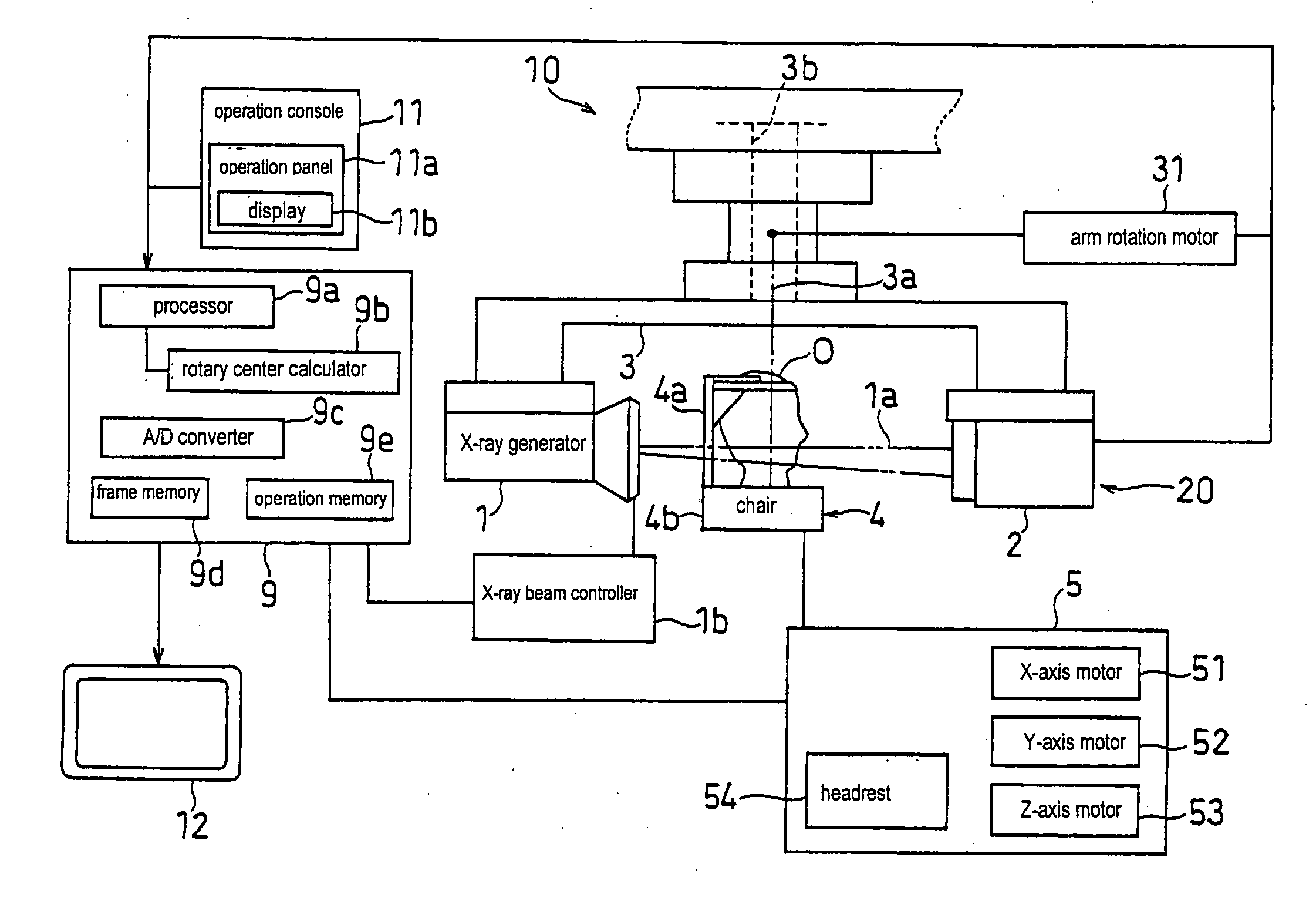
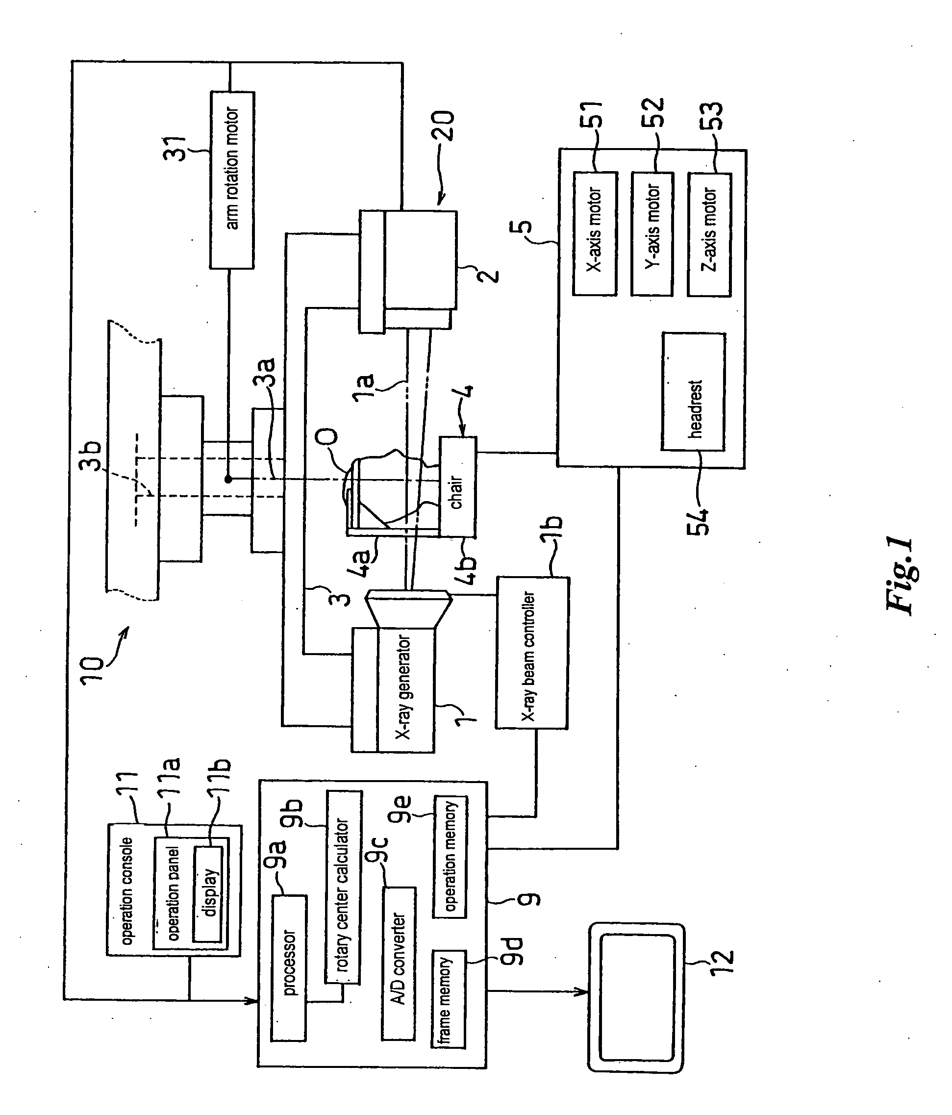
[0083]FIG. 1 shows an entire construction of one embodiment of the X-ray CT apparatus of the present invention.

[0084] The X-ray CT apparatus 20 is comprised of a rotary arm 3 suspending an X-ray generator 1 and a two-dimensional X-ray image sensor 2 so as to face each other, an object holding means 4 for fixing an object, an object moving means 5 for horizontally moving the object holding means 4, an image processing means 9 controlling the apparatus entirely, a main frame 10, and an operation panel 11 with a display means 11b for simply showing an operational guide of the apparatus 20 and with an operation panel 11a for operating according to the display on the display means 11b.

[0085] In this embodiment, the rotary arm 3 is constructed as an X-ray radiation means and the X-ray generator 1 has an X-ray beam controller 1b for controlling the energy of generated X-ray beams...


PUM

PropertyMeasurementUnit
heightaaaaaaaaaa
diameteraaaaaaaaaa
computed tomographyaaaaaaaaaa

Abstract

An X-ray CT apparatus which executes a first X-ray tomography on a sectional plane having a desirable thickness in an object to be examined (O) with the object interposed between an X-ray generator (1) and a two-dimensional X-ray image sensor (2) provided so as to hold their mutual facing positional relation, and also executes a second X-ray tomography for obtaining a CT image of the interested area of the object (O), wherein the first X-ray tomography is executed on the object (O) while the object (O) is held and fixed by an object holding means (4) with the center of the orbit of the X-ray circulating radiation fixed, and while the object holding means (4) is moved by an object moving means (5) along the X-ray sectional image forming path according to the rotary angle of the X-ray circulating radiation.

Description

TECHNICAL FIELD [0001] The present invention relates to an X-ray CT apparatus in which the center of the orbit of X-ray circulating radiation is fixed on an imaging interested area in an object, X-ray is radiated in a circulating manner only on the imaging interested area, and the second X-ray sectional image which is an X-ray image obtained by reconstructing an X-ray absorption coefficient of the imaging interested area, and further, the first X-ray sectional image such as a curved plane X-ray sectional image and a flat plane X-ray sectional image can be produced. BACKGROUND ART [0002] In the field of dental treatment such that a local area to obtain CT image, namely an imaging interested area, is only a part of a relatively small area like a human head, for example one or two teeth, an X-ray CT apparatus in which an X-ray rotary center is fixed on the imaging interested area, X-ray is radiated in a circulating manner only on the imaging interested area and the image of the X-ray a...

Claims


Application Information

Patent Timeline
Patent Type & Authority Applications(United States)
IPC IPC(8): A61B6/04A61B6/14
CPCA61B6/04A61B6/548A61B6/14A61B6/0421
Inventor SUZUKIYOSHIMURA, TAKAHIROYOSHIDA, MASANOBUOTSUKA, MASANORIYOSHIKAWA, HIDEKI
Owner MORITA MFG CO LTD
Why Eureka
Try Eureka