Driver drill

a technology of drivers and drill bits, which is applied in the direction of portable drilling machines, gearing, manufacturing tools, etc., can solve the problems of inability to eliminate the influence of the tolerances of the housing and the cap, inability to prevent the possibility of the occurrence of erroneous clutch operation in the drill mode, and inability to effectively prevent the clutch operation of the drill mode. , to achieve the effect of excellent reliability, outstanding usability and effective prevention of clutch operation

Active Publication Date: 2005-07-14
MAKITA CORP
View PDF11 Cites 39 Cited by
  • Summary
  • Abstract
  • Description
  • Claims
  • Application Information

AI Technical Summary

Benefits of technology

[0010] According to the first aspect of the present invention, the movement of the intermediate member is regulated by the interfering unit provided with the gear case which holds the intermediate member. Due to this, the intermediate member is securely locked without being influenced by tolerances among the components. Therefore, erroneous clutch operation in a drill mode can be effectively prevented, and excellent reliability can be achieved.
[0011] According to the second aspect of the present invention, in addition to the effect of the first aspect, any one of three operation modes, that is, the clutch mode, drill mode, and the percussion mode, can be selected only by rotative operation of the operating member. Therefore, outstanding usability can be achieved.
[0012] According to the third aspect of the present invention, in addition to the effect of the first or second aspect, torque adjustment in the clutch mode is performed by the second operating means, which is provided separately from the operating member. Therefore, switching of the operation mode can be performed irrespective of the position where torque adjustment is performed by the second operating member. Furthermore, the operation mode is prevented from being erroneously switched at the time of torque adjustment.

Problems solved by technology

That is, when a load on the spindle is increased to exceed a biasing force of the coil spring, the internal gear idles to interrupt the transfer of rotation to the spindle.
Therefore, even with the clutch mechanism, an influence of the tolerances of the housing and the cap cannot be eliminated.
After all, the possibility of the occurrence of erroneous operation of the clutch in the drill mode cannot be prevented.

Method used


Image

  • Driver drill
  • Driver drill
  • Driver drill

Examples


Embodiment Construction

[0026] An embodiment according to the present invention is described below based on the drawings.

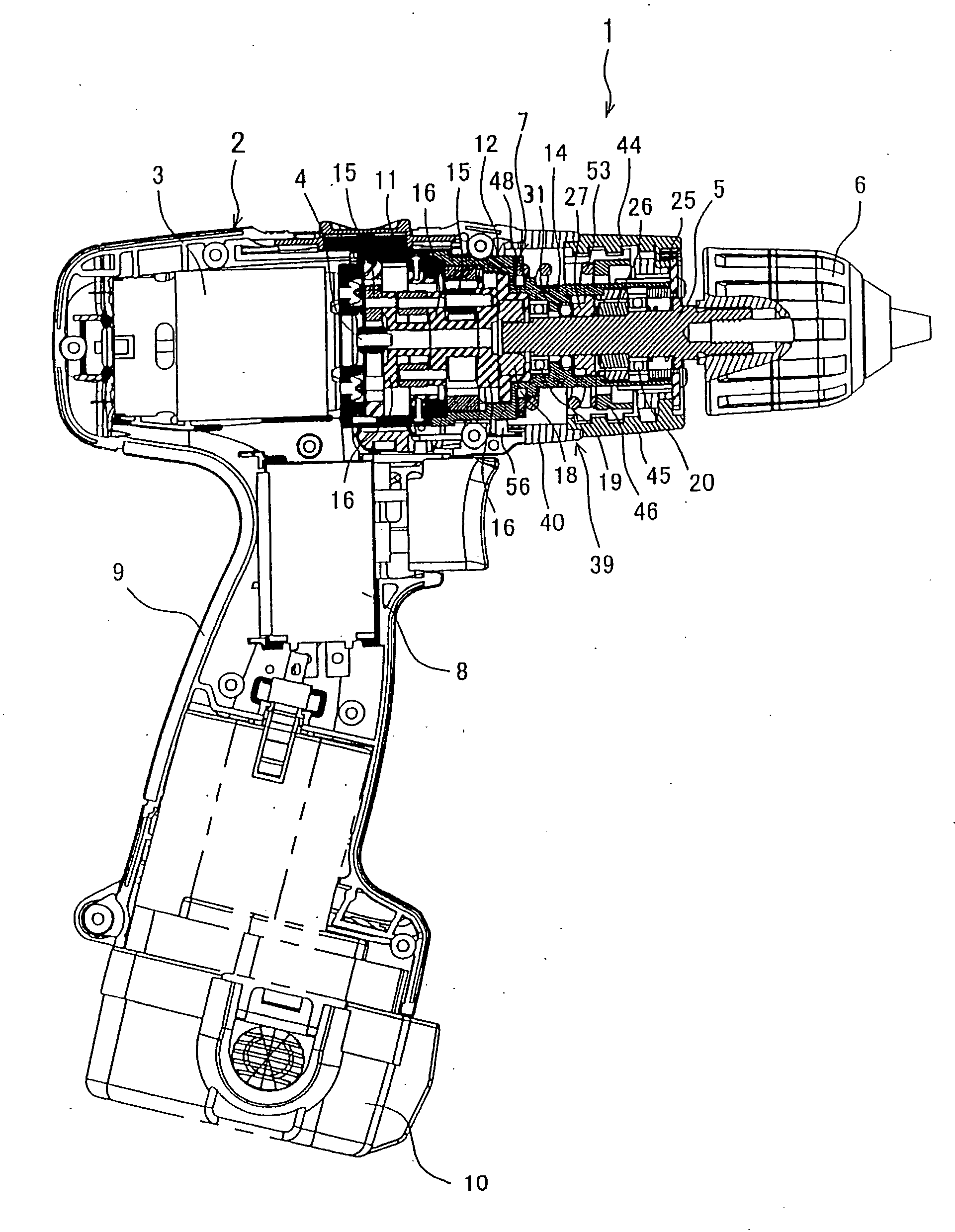
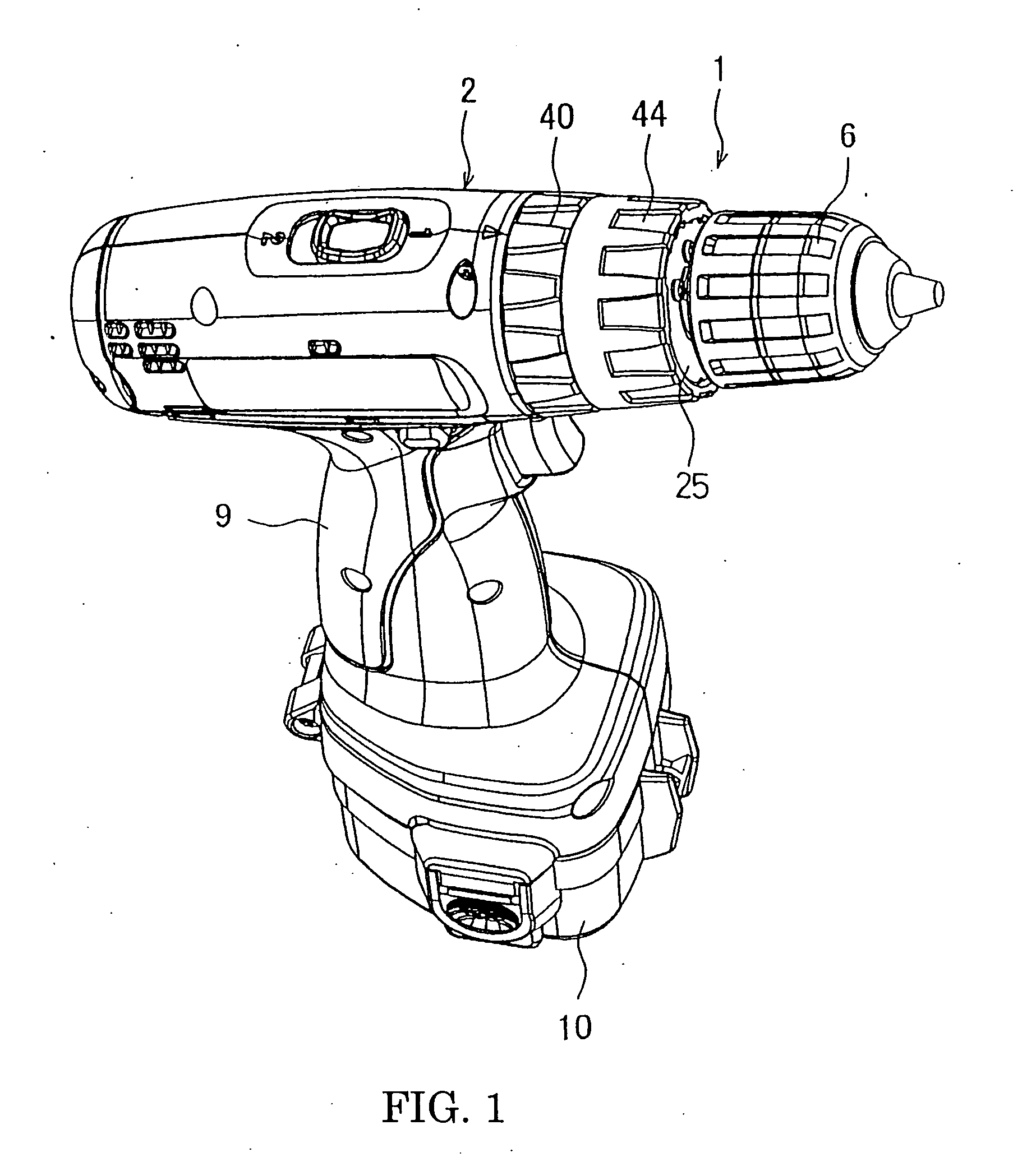
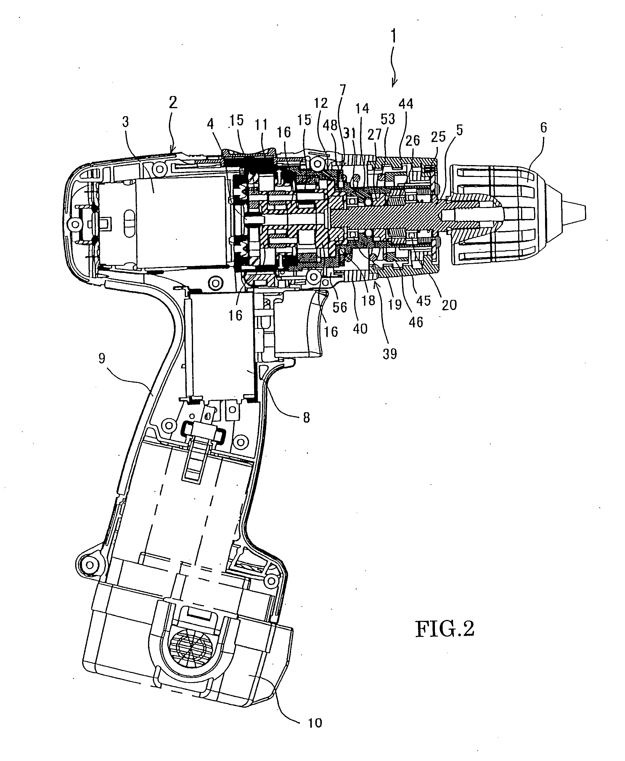
[0027]FIG. 1 is a perspective view of a percussion driver drill, which is an example of a driver drill, and FIG. 2 is a vertical section view of the percussion driver drill. A percussion driver drill 1 has a motor 3 accommodated in a body housing 2 formed of a pair of right and left half-housings. From an output shaft 4 of the motor 3, rotation is transferred to a spindle 5 through a gear assembly 7 mounted at the front side (at the right in FIGS. 1 and 2) in the body housing 2 and from which the spindle 5 protrudes forward. At the front end of the spindle 5, a drill chuck 6 whose tip can hold a bit is provided. The reference number 8 denotes a switch for driving the motor 3, and the reference number 9 denotes a handle. Moreover, the reference number 10 denotes a battery pack as a power source mounted at the lower end of the handle 9.

[0028] As shown in FIGS. 3 and 4, the gear assembly ...


PUM

PropertyMeasurementUnit
movementaaaaaaaaaa
pressing forceaaaaaaaaaa
diameteraaaaaaaaaa

Abstract

A driver drill that can effectively prevent erroneous clutch operation in a drill mode is provided. A flat washer positioned between steel balls for locking an internal gear and a coil spring is rotatable by rotative operation of a mode-change ring. Also, protruding streaks are provided on a small-diameter unit of a second gear case around which a flat washer is externally mounted. The protruding streaks interfere with internal projections on an inner circumference of the flat washer at its predetermined rotating position to regulate a forward movement of the flat washer. When a drill mode is selected with the mode-change ring, the flat washer is locked by the protruding streaks.

Description

BACKGROUND OF THE INVENTION [0001] This application claims the benefit of Japanese Patent Application Number 2004-4610 filed Jan. 9, 2004, the entirety of which is incorporated by reference. FIELD OF THE INVENTION [0002] The present invention relates to a driver drill usable with a selection of a clutch mode and a drill mode. DESCRIPTION OF THE RELATED ART [0003] In a driver drill, firstly, a clutch mode is achieved in a planetary gear reduction mechanism disposed between a motor and a spindle with a structure in which one of internal gears interlocked with the circumference of planetary gears can be rotated within a housing. Also, the internal gear is pressed and locked by a coil spring through steel balls held by a gear case accommodating the planetary gear reduction mechanism and engaged with an end face of the internal gear and through a washer externally provided to the gear case so as to abut on the steel balls. That is, when a load on the spindle is increased to exceed a bias...

Claims


Application Information

Patent Timeline
Patent Type & Authority Applications(United States)
IPC IPC(8): B23B45/00B23B45/16B25B21/00B25B23/14B25D16/00B25F5/00F16D43/20F16H1/46
CPCB23B45/008B25D16/006B25B23/141B25B21/00
Inventor UMEMURA, SHINGOMIURA, MASAHIKO
Owner MAKITA CORP
Why Eureka
Try Eureka