Exhaust air removal system

a technology of exhaust air and removal system, which is applied in ventilation systems, heating types, electrical apparatus casings/cabinets/drawers, etc., can solve the problems of rack-mounted equipment that consumes electrical power and generates heat, rack-mounted equipment that is housed within an enclosure is particularly vulnerable to heat build-up and hot spots, and achieves the effects of reducing the extent to which exhaust air mixes, reducing the degree of mixing, and eliminating or

Inactive Publication Date: 2005-08-04
SCHNEIDER ELECTRIC IT CORP
View PDF25 Cites 322 Cited by
  • Summary
  • Abstract
  • Description
  • Claims
  • Application Information

AI Technical Summary

Benefits of technology

[0025] The fan unit can draw exhaust air vented from rack-mounted equipment and can contain and vent exhaust air to an area external to the rack, e.g., an external exhaust duct or plenum connected to the fan unit. The fan unit can thereby help to eliminate or to at least minimize / reduce the extent to which exhaust air mixes with ambient air of an equipment room or data center. The fan unit can help to eliminate or to at least minimize / reduce undesirable recirculation of exhaust air to equipment. By helping to eliminate or to at least minimize / reduce mixing of exhaust air with ambient air and recirculating exhaust air to equipment, the fan unit can help to prevent or to minimize / reduce a thermal gradient of inlet temperatures of ambient air drawn into equipment from an intake side of equipment. Temperatures of ambient air drawn into equipment at a top portion of a rack thereby are not substantially higher / lower than temperatures of ambient air drawn into equipment at a bottom portion of the rack.
[0026] By removing and containing exhaust air, the fan unit can help to maintain ambient air temperature, e.g., within a range of from about 60° F. to about 70° F., and to enable rack-mounted equipment to rely on ambient air to meet its cooling requirements. Cooling and supplying ambient air within this range can help to eliminate or to at least minimize / reduce condensation and humidification problems typically associated with supplying cooling air at relatively low temperatures, e.g., 55° F. In addition, cooling and supplying ambient air within this range can help to eliminate or to at least minimize / reduce condensation and humidification problems and costs typically associated with supplying cooling air at relatively low temperatures, e.g., 55° F.
[0027] Without a need for cooling air at low temperatures, the system and method employing the fan unit can avoid a double or raised floor construction that can be used to provide cooling air at relatively low temperatures, e.g., 55° F., and to supply air directly into equipment racks and enclosures. The system and method, thus, can avoid the cost disadvantages associated with the operation and maintenance of raised floor cooling systems and methods. In addition, the system and method employing the fan unit can avoid the costs of reconfiguring equipment rooms and retrofitting cooling equipment and racks that may be required with raised floor cooling systems and methods.
[0028] Removing exhaust air vented by rack-mounted equipment with the fan unit can provide flexibility to accommodate a wide variation in electrical power drawn by rack-mounted equipment and a consequent wide variation in exhaust air produced by the equipment. The fan unit can be quickly and easily installed to and detached from an individual equipment rack and / or enclosure, as well as installed to and detached from an external exhaust duct, e.g., a duct coupled to the fan unit to vent exhaust air to a dropped ceiling exhaust plenum for removal of exhaust air from an equipment room or data center.
[0029] Control of fan-speeds can help to eliminate or to at least minimize / reduce a potential for rack-mounted equipment to draw ambient air at a flow rate greater or less than required to meet its cooling needs. A risk of rack-mounted equipment receiving too much or too little ambient air for cooling, therefore, can be eliminated or at least minimized / reduced. Control of fan-speeds can also help to avoid or to at least minimize / reduce a risk of returning exhaust air to an air conditioning or cooling system at a rate that can exceed or overcome a capacity of the air conditioning or cooling system. Fan-speeds can be controlled and adjusted in accord with measured values of a power load of equipment, and / or detected internal temperatures of equipment.
[0030] In addition, control of air flow and internal temperatures of rack-mounted equipment can be protected against power outages and power irregularities to prevent heat build up and overheating. Advantages of aspects of the invention can be provided to new or existing standard-dimensioned or nonstandard-dimensioned racks and enclosures with minimal or no retrofitting of racks or enclosures.

Problems solved by technology

Most rack-mounted communications and information technology equipment consumes electrical power and generates heat.
Heat produced by rack-mounted equipment can have adverse effects on the performance, reliability and useful life of the equipment components.
In particular, rack-mounted equipment housed within an enclosure is particularly vulnerable to heat build-up and hot spots produced within the confines of the enclosure during operation.
The cooling systems and methods that require a raised floor construction typically do not efficiently meet the cooling requirements of rack-mounted equipment.
In particular, racks that include high power equipment having a thermal exhaust air output above 5 kW and up to 10 kW present a particular challenge for such systems and methods.
Such a floor configuration would be difficult to achieve in equipment rooms crowded with racks and enclosures, and impossible to implement if racks and enclosures are arranged side-by-side in rows.
For typical rack spacing, this places a limit on the density of equipment that can be achieved.
In this context, raised floor air cooling systems and methods are inflexible and can typically only be reconfigured and / or retrofitted to service rearranged, relocated and / or newly installed equipment racks at considerable cost.
Raised floor configurations cannot easily and inexpensively accommodate the manner by which users typically deploy equipment racks and reconfigure equipment rooms and data centers to meet their new or changing needs.
In addition, cooling systems and methods that require raised floor construction lack physical flexibility and portability to operatively account for a wide variation in electrical power consumption between different racks and enclosures in an equipment room, and, in particular, between racks and enclosures located in the same row.
Cooling systems and methods that rely upon raised floor air passageways and open floor tiles, grills or vents to supply cool air cannot easily and inexpensively vary or concentrate cool air to those high power racks that consume relatively large amounts of electrical power and have a high thermal air exhaust output.
In addition, newly installed equipment may draw more electrical power than replaced or existing equipment to create thermal problem areas in functioning equipment rooms.
Further, cooling systems and methods that depend upon raised floor construction cannot physically accommodate specific areas in equipment rooms with thermal problems.
For example, such systems and methods cannot overcome exhaust problems where hot and warm exhaust air is not effectively vented from an equipment room and / or returned to an air conditioning or cooling system without considerable expense to reconfigure and / or retrofit the air systems and / or the racks and enclosures.
Such exhaust problems can also cause hot and warm exhaust air to recirculate to racks and enclosures, raising operating temperatures of equipment and, in particular, equipment with high power consumption and / or equipment located in areas of an equipment room with thermal problems.
Similarly, raised floor cooling systems and methods cannot account for local thermal problems where hot and warm exhaust air from one rack is drawn into adjacent and / or proximate racks causing equipment overheating.
Raised floor cooling systems and methods cannot easily retrofit to existing cooling systems of an equipment room or data center or to existing equipment racks.
Air cooling systems and methods that require raised floor configurations also reduce available headroom in equipment rooms and data centers.
Wires housed within air passageways below raised floors are difficult to access.
In addition, such air passageways are difficult to clean.
Open floor tiles and floor grills or vents also pose a safety risk to personnel.
In addition, raised floor construction presents a risk of collapse during earthquake.

Method used


Image

  • Exhaust air removal system
  • Exhaust air removal system
  • Exhaust air removal system

Examples


Embodiment Construction

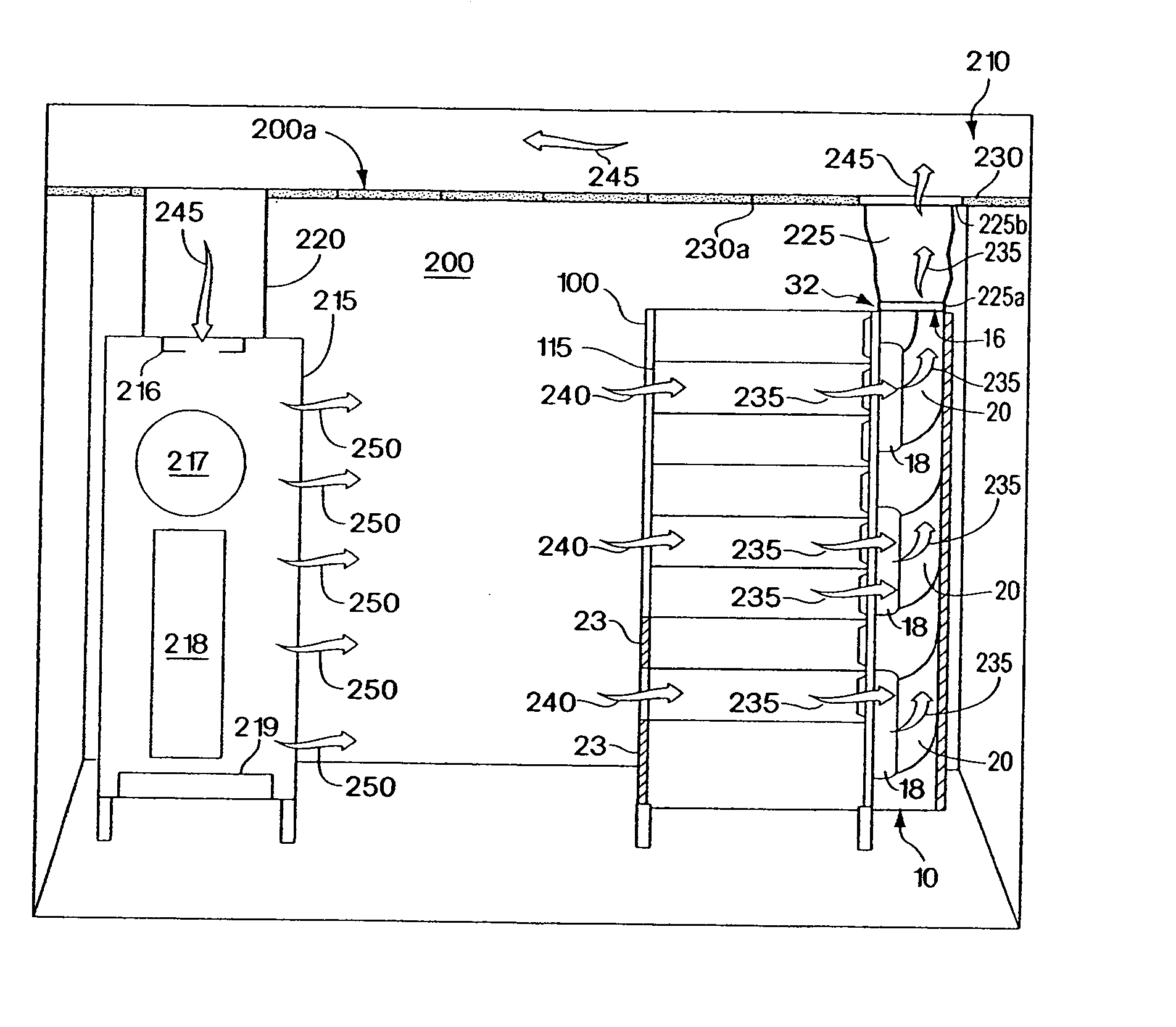
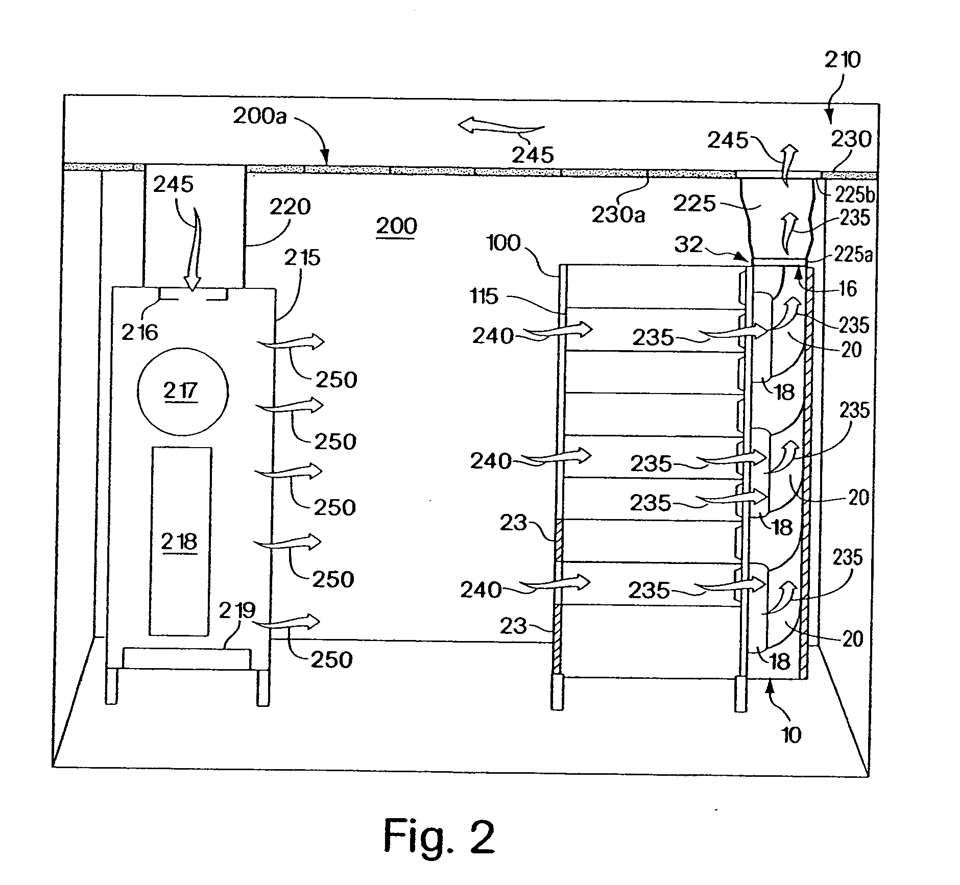
[0049] Illustrative embodiments of the invention provide an exhaust air removal system and method for use with equipment rooms and data centers in which communications and information technology equipment is stored and operated. More particularly, an exhaust air removal system and method are provided to remove undesirable thermal exhaust air produced by equipment, such as rack-mounted servers, CPUs and other electronic equipment, during operation of the equipment. The exhaust air removal system is constructed and arranged to connect to an equipment rack and / or a rack enclosure. When connected to an equipment rack and / or enclosure, the system is disposed and configured to remove thermal exhaust air output from the rack by drawing and containing exhaust air vented from the rack and venting the exhaust air to an area external to the rack and / or the enclosure. The system is constructed and arranged to remove exhaust air vented by equipment in a rack and / or enclosure to help minimize or ...


PUM


Abstract

An exhaust air removal system and method for use with a rack or enclosure containing equipment is provided. The system and method are configured for removal of exhaust air vented from equipment during operation to thereby remove heat from the equipment. In one aspect, the system includes a fan unit preferably configured to serve as a back door of an equipment rack or enclosure and configured to provide access to an interior of the rack or enclosure. The fan unit provides multiple fans coupled to internal exhaust ducts that are arranged to draw and to remove exhaust air vented from rack-mounted equipment. The fan unit is further configured to vent exhaust air to an area external to a rack or enclosure, such as an external exhaust duct or plenum. Removal of hot and warm exhaust air vented from rack-mounted equipment enables the equipment to operate effectively, drawing sufficient amounts of cooling air to meet its cooling requirements. The fan unit is constructed for portability and for easy attachment to and removal from a rack or enclosure, providing flexibility in handling equipment exhaust needs.

Description

FIELD OF THE INVENTION [0001] The invention relates to an exhaust air removal system for removing thermal exhaust air produced by equipment during operation. BACKGROUND OF THE INVENTION [0002] Communications and information technology equipment is commonly designed for mounting to racks and for housing within enclosures. Equipment racks and enclosures are used to contain and to arrange communications and information technology equipment, such as servers, CPUs, internetworking equipment and storage devices, in small wiring closets as well as equipment rooms and large data centers. An equipment rack can be an open configuration and can be housed within a rack enclosure. A standard rack typically includes front-mounting rails to which multiple units of equipment, such as servers and CPUs, are mounted and stacked vertically, and typically has a footprint of about 23 by 42 inches. The equipment capacity of a standard rack relates to the height of the mounting rails. The height is set at ...

Claims


Application Information

Patent Timeline
Patent Type & Authority Applications(United States)
IPC IPC(8): H05K7/20
CPCH05K7/20836H05K7/20736
Inventor JOHNSON, ROLLIE R.RASSMUSSEN, NEIL
Owner SCHNEIDER ELECTRIC IT CORP
Why Eureka
Try Eureka