Internal combustion engine

a combustion engine and internal combustion technology, applied in the direction of machines/engines, output power, mechanical apparatus, etc., can solve the problems of many problems in the engine, high startability is required, and oil is caused to enter the cylinder from the circumferen

Active Publication Date: 2010-03-18
MITSUBISHI MOTORS CORP
View PDF1 Cites 2 Cited by
  • Summary
  • Abstract
  • Description
  • Claims
  • Application Information

AI Technical Summary

Benefits of technology

[0013]According to an aspect of the invention, there is provided an internal combustion engine including: a cam shaft, having an inlet cam for opening and closing an inlet valve; a variable valve train mechanism, configured to receive a cam displacement of the inlet cam so as to vary a driving output for driving the inlet valve continuously from a maximum valve lift to a minimum valve lift, while narrowing a valve opening period, so as to match the driving output with a running condition of the internal combustion engine; and a control part, configured to control the variable valve train mechanism so as to set-a valve lift of the inlet valve to a starter valve lift when starting the internal combustion engine in a cold state, wherein the starter valve lift is formed so that a valve opening period of the inlet valve is set to encompass an overall area of an induction stroke period of the internal combustion engine from a top dead center to a bottom dead center of the induction stroke period.
[0056]Therefore, in the second embodiment, the stable cold fast idle can be obtained while suppressing the discharge of unburnt fuel mixture. Moreover, since the actual compression ratio is reduced and the mixing of air and fuel is improved, there occurs no rise in combustion temperature that would otherwise occur in conjunction with the mixture being made lean locally, and the discharge of oxides of nitrogen is also suppressed.
[0056]Therefore, in the second embodiment, the stable cold fast idle can be obtained while suppressing the discharge of unburnt fuel mixture. Moreover, since the actual compression ratio is reduced and the mixing of air and fuel is improved, there occurs no rise in combustion temperature that would otherwise occur in conjunction with the mixture being made lean locally, and the discharge of oxides of nitrogen is also suppressed.

Problems solved by technology

In particular, a high startability is required for a cold engine in which fuel is difficult to vaporize.
Because of this, there is caused a fear that oil is caused to enter the cylinder from the circumference of the piston due to the depression so produced in the cylinder.
In addition, the valve lift amount of the inlet valve which is slightly too small tends to easily call for insufficiency of intake air by volume, leaving many problems in the engine.
This then causes a fundamental problem that the actual compression ratio within the cylinder is reduced.
Moreover, since a period when the exhaust valve is opened and the inlet valve is closed is formed in an area spreading further than the top dead center of the induction stroke period, a behavior is generated in which combustion gases are retaken in from an initial combustion on, and combustion tends to become unstable easily, resulting in a fear that a misfire may take place.
Because of this, conversely, there is also caused a fear that the startability of the engine is reduced.
On top of that, the delay of the phase of the exhaust valve delays the opening of the exhaust valve, this also leading to a problem that the effect is eliminated of increasing the temperature of a catalyst for purifying exhaust gases of the engine.
However, with the variable valve train having the construction described above, although valve characteristics matching running or operating conditions of the engine can be obtained, it becomes difficult due to its variability that a valve lift for a fast idle of a cold engine is compatible with a valve lift for starting the cold engine.

Method used


Image

  • Internal combustion engine
  • Internal combustion engine
  • Internal combustion engine

Examples


first embodiment

[0026]Hereinafter, the invention will be described based on a first embodiment which is shown in FIGS. 1 to 6.

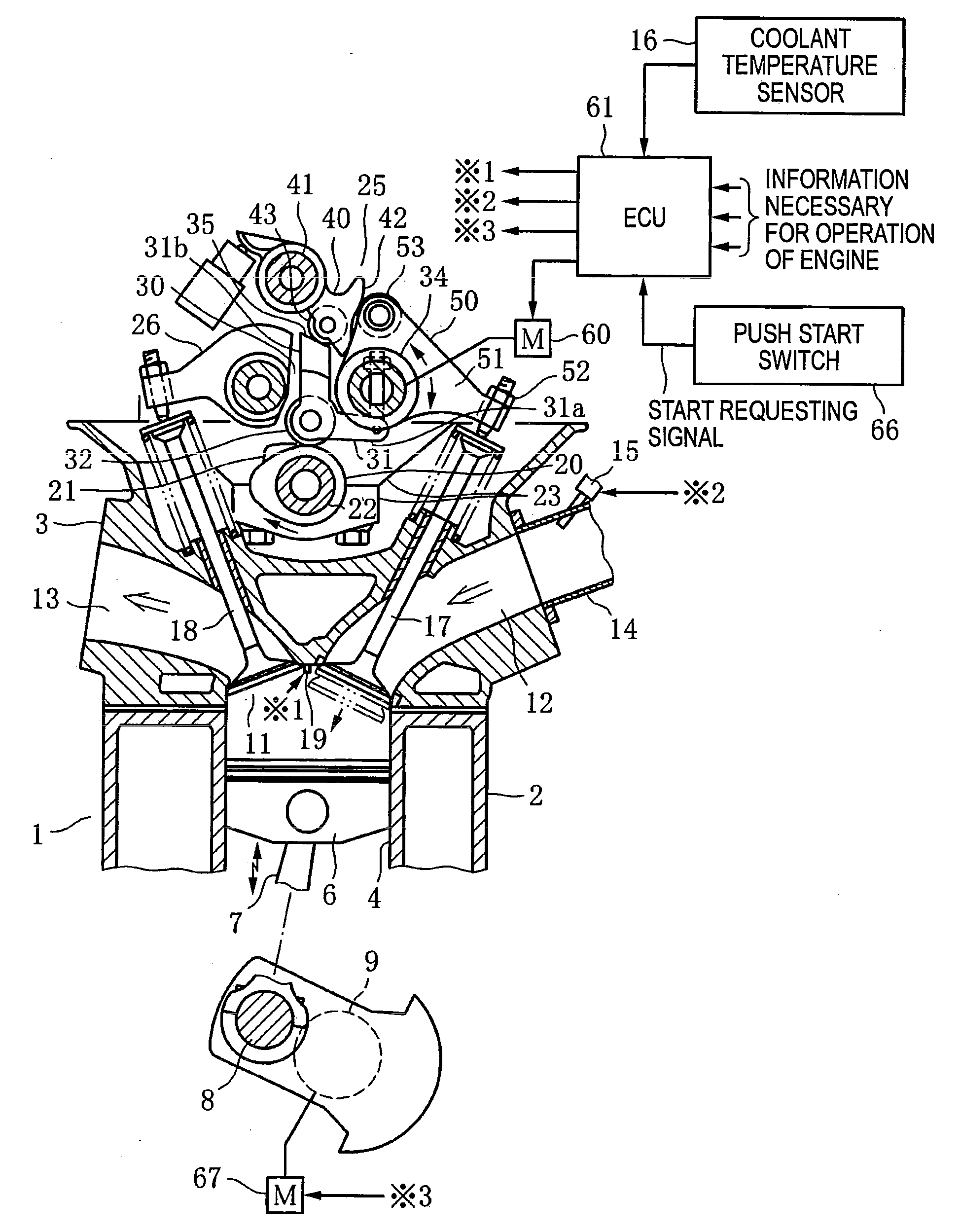
[0027]FIG. 1 shows schematically part of a reciprocating SOHC engine 1 which is an internal combustion engine and a control system of the engine 1.

[0028]Firstly, the engine 1 will be described. In FIG. 1, reference numeral 2 denotes a cylinder block and reference numeral 3 denotes a cylinder head which is mounted on an upper portion of the cylinder block 2. Cylinders 4 (only part thereof being shown) are formed in the cylinder block 2 of these constituent components of the engine 1. A piston 6 is accommodated within the cylinder 4 so as to reciprocate therein. This piston 6 is connected to a crankshaft 9 which is provided at a lower portion of the cylinder block 2 via a connecting rod 7 and a crank pin 8.

[0029]A combustion chamber 11 is formed below a lower surface of the cylinder head 3. An inlet port 12 and an exhaust port 13 are formed on sides of the combustion chamber 1...

second embodiment

[0050]FIGS. 7 to 9 show the invention.

[0051]This embodiment is a modified example to the first embodiment, which is a device imparted to the large valve lift α for fast idle which is used for the fast idle in the cold state which follows the cold start, which device is such as to suppress the discharge of exhaust gases containing much unburnt fuel mixture.

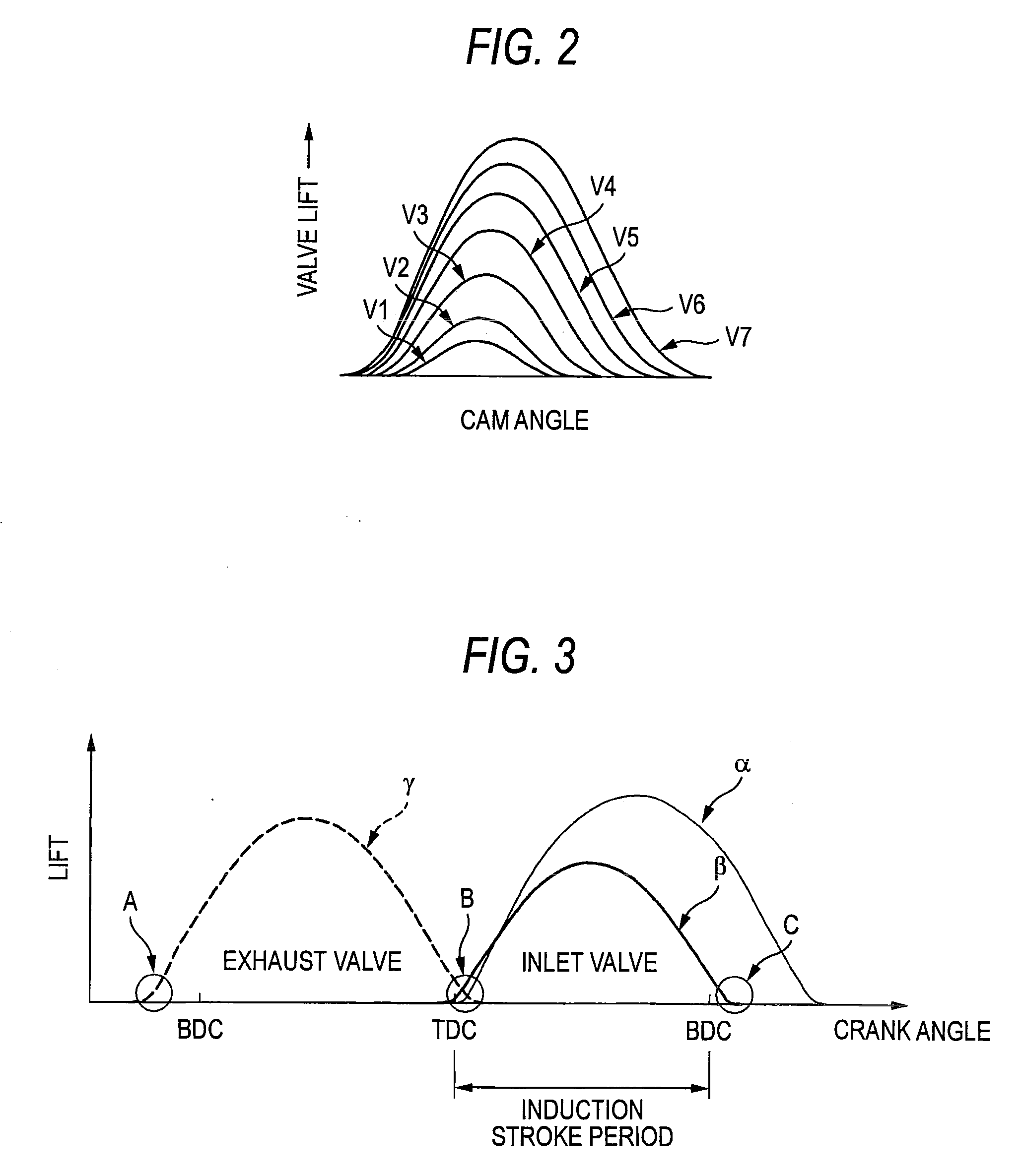
[0052]Namely, a lift curve of a valve opening period having a valve opening position which lies forwards of a top dead center of an induction stroke period is adopted in a valve lift α for a fast idle in a cold state. In particular, a setting is used in a valve lift α in which the valve opening position of an inlet valve 17 is advanced further forwards from a top dead center of an induction stroke period than the valve opening position of the inlet valve 17 used for the cold start, and a valve closing position of the inlet valve 17 is delayed to a point which lies beyond a bottom dead center of the induction stroke period by such a...


PUM


Abstract

An internal combustion engine includes: a variable valve train mechanism, configured to receive a cam displacement of an inlet cam so as to vary a driving output for driving an inlet valve continuously from a maximum valve lift to a minimum valve lift so as to match the driving output with a running condition of the internal combustion engine; and a control part, configured to control the variable valve train mechanism so as to set a valve lift of the inlet valve to a starter valve lift when starting the internal combustion engine in a cold state. The starter valve lift is formed so that a valve opening period of the inlet valve is set to encompass an overall area of an induction stroke period of the internal combustion engine from a top dead center to a bottom dead center of the induction stroke period.

Description

BACKGROUND[0001]1. Field of the Invention[0002]The present invention relates to an internal combustion engine in which the valve characteristics of an inlet valve are made variable by the use of a variable valve train.[0003]2. Description of the Related Art[0004]A good startability is required for a reciprocating engine (internal combustion engine) which is mounted on a motor vehicle (a vehicle). In particular, a high startability is required for a cold engine in which fuel is difficult to vaporize.[0005]On the other hand, there is an engine disclosed in JP-A-2003-129812 in which a variable valve train of a variable valve lift type is mounted on a cylinder head for variably controlling the valve characteristics of an inlet valve so as to match them with a running condition of the engine in which variable valve train a valve lift of the inlet valve is made to vary continuously from a maximum valve lift to a minimum valve lift based on a maximum lift center position with a valve openi...

Claims


Application Information

Patent Timeline
Patent Type & Authority Applications(United States)
IPC IPC(8): F01L1/34
CPCF01L13/0021F01L13/0063F01L2800/01Y10T74/2107F02D13/0261Y02T10/18F02D13/023Y02T10/12
Inventor YOSHIKA, DAISUKEMURATA, SHINICHITODA, HITOSHITAKAGAKI, MASAYUKI
Owner MITSUBISHI MOTORS CORP
Why Eureka
Try Eureka