Image recording apparatus

a recording apparatus and image technology, applied in the direction of spacing mechanisms, printing mechanisms, printing, etc., can solve the problems of wasteful space, large height of image recording apparatus, large image recording apparatus, etc., and achieve the effect of accurately setting the gap between a recording head and a recording medium, reducing cost and reducing waste of spa

Active Publication Date: 2005-09-08
BROTHER KOGYO KK
View PDF13 Cites 42 Cited by
  • Summary
  • Abstract
  • Description
  • Claims
  • Application Information

AI Technical Summary

Benefits of technology

[0007] According to the structure disclosed in JP-A-2002-254746, since an additional member is not required for a guide shaft and the like, the cost can be reduced. However, in order to accurately guide the carriage in the main scanning direction and a sub-scanning direction orthogonal thereto, and to accurately set a gap between a recording head and a recording medium, it is required that the guide plates are accurately and firmly attached to the main frame. Besides, although a maintenance unit part for maintenance of the recording head is disposed at one end part in the main scanning direction, when the length of the main frame in the main scanning direction is made long for that purpose, there arise a problem that a wasteful space is produced and the image recording apparatus becomes large. Further, in the case where a paper feed cassette is disposed below the main frame, a space for vertical movement of a paper feed roller is required, and there arises a problem that the height size of the image recording apparatus becomes large.

Problems solved by technology

Besides, although a maintenance unit part for maintenance of the recording head is disposed at one end part in the main scanning direction, when the length of the main frame in the main scanning direction is made long for that purpose, there arise a problem that a wasteful space is produced and the image recording apparatus becomes large.
Further, in the case where a paper feed cassette is disposed below the main frame, a space for vertical movement of a paper feed roller is required, and there arises a problem that the height size of the image recording apparatus becomes large.

Method used


Image

  • Image recording apparatus
  • Image recording apparatus
  • Image recording apparatus

Examples


Embodiment Construction

[0037] Now, an embodiment of the invention will be described.

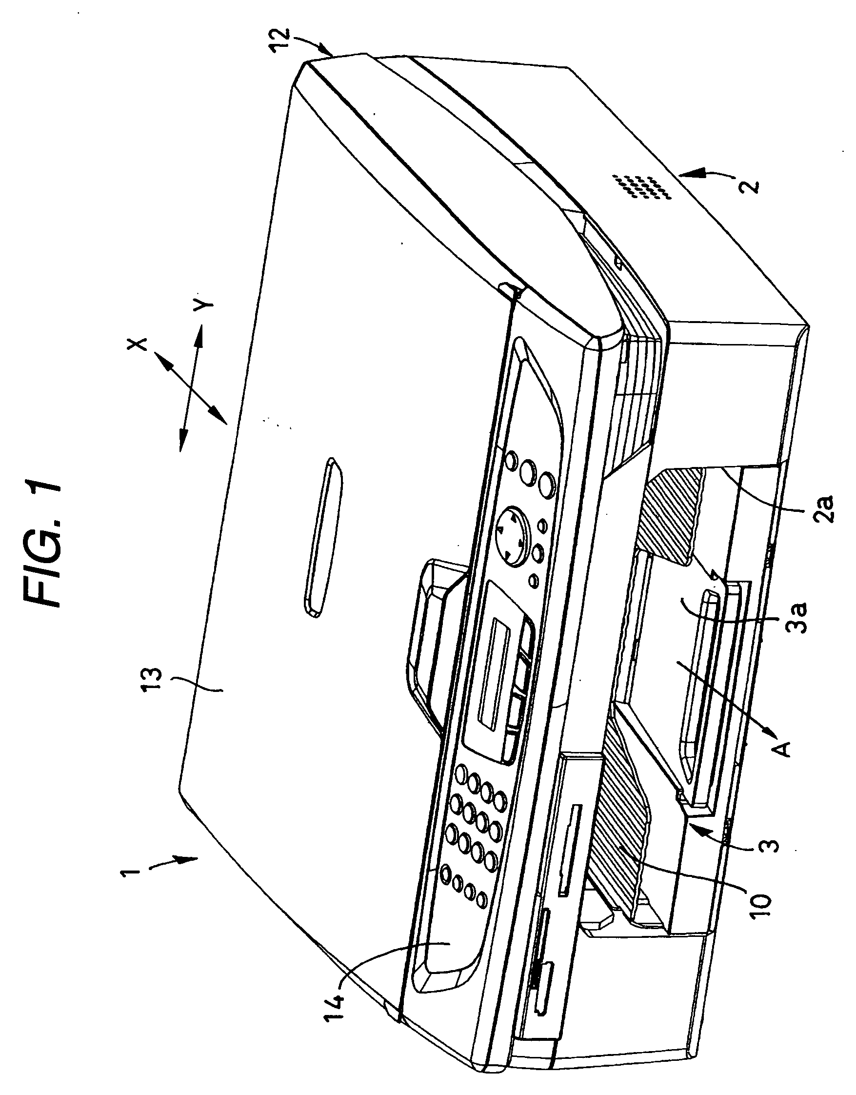
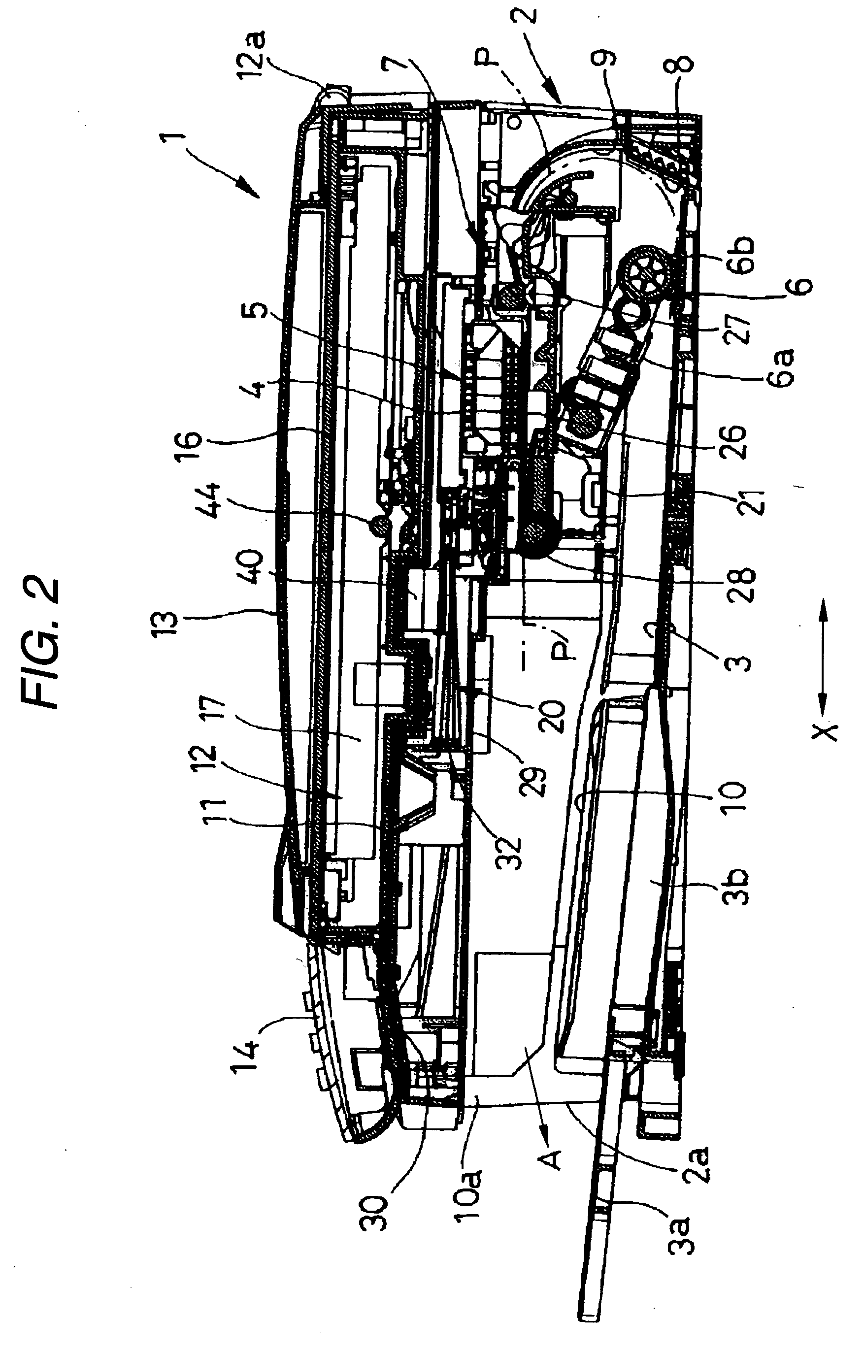
[0038] An image recording apparatus 1 of this embodiment is a multi function device (MFD) having a printer function, a copy function, a scanner function and a facsimile function, to which the invention is applied. As shown in FIGS. 1 and 2, at a bottom part of a housing 2 which is a recording apparatus main body of synthetic resin in the image recording apparatus 1 and is made of an injection molded part of synthetic resin, a paper feed cassette 3 is disposed which can be inserted through an opening part 2a on the front side (left side in FIG. 2).

[0039] In this embodiment, the paper feed cassette 3 is made to have such a form that plural sheets P, each of which is a recording medium and is cut into, for example, A4 size, letter size, legal size, postcard size or the like, can be stacked (deposited) and housed in such a manner that its short side extends in a direction (direction orthogonal to the surface of the sheet of ...


PUM


Abstract

An image recording apparatus includes: a carriage that carries a recording head capable of recording an image on a recording medium and reciprocates in a main scanning direction; a substantially box-shaped main frame having an open upper side and a pair of side plates extending in a sub-scanning direction orthogonal to the main scanning direction; and first and second guide members over which the carriage extends and by which the carriage is guided, the first and second guide members being disposed to be apart from each other by a predetermined distance in the sub-scanning direction, extended in the main scanning direction at the upper side of the main frame and fixed to the pair of side plates.

Description

BACKGROUND OF THE INVENTION [0001] 1. Field of the Invention [0002] The present invention relates to an image recording apparatus of an ink-jet type or the like, and more particularly to a structure of a main frame to house a main part. [0003] 2. Description of the Related Art [0004] A conventional image recording apparatus of an ink-jet type, a thermal-head type or the like is such that as disclosed in JP-A-11-246055 (see FIG. 1 and FIG. 5) or JP-A-2001-260475 (see FIGS. 1 to 4), cylindrical guide shafts to support a carriage carrying a recording head in such a manner that the carriage can reciprocate in a main scanning direction, a paper feed roller, a paper discharge roller, and the like are disposed in the inside of a box-type main frame made of a metal plate and fixed in a synthetic resin housing of the image recording apparatus. Both ends of these shafts are attached to right and left side plates of the main frame so as to be pivotally supported. [0005] Besides, the structure ...

Claims


Application Information

Patent Timeline
Patent Type & Authority Applications(United States)
IPC IPC(8): B41J19/00B41J2/01B41J19/20
CPCB41J19/00
Inventor SAMOTO, KENJISUGIURA, TOSHIO
Owner BROTHER KOGYO KK
Why Eureka
Try Eureka