Loft flooring system

a flooring system and floor technology, applied in the field of floor flooring systems, can solve the problems of energy waste, affecting us all, and energy efficiency of buildings, and achieve the effects of high stability and security, high level of versatility, and quick installation

Active Publication Date: 2013-09-19
NOMINAL SUM
View PDF18 Cites 8 Cited by
  • Summary
  • Abstract
  • Description
  • Claims
  • Application Information

AI Technical Summary

Benefits of technology

[0014]The described system assembled from legs and beams in rows traversing the joists is remarkably quick to install and is stable and safe. By contrast, we have found that simpler arrangements that use arrays of legs as pedestals for direct support of flooring panels / boards without use of the beams or which have beams that extend longitudinally of the joists but not traversing them are generally unstable and unsafe and vulnerable to catastrophic collapse. Furthermore, more complex inter-connected arrangements, where the rows spanning joists are inter-linked by extra spanning elements or other support members for the floor fitted extending from one row to the next (eg rectangular table type framework arrangements) are not only more expensive and more time-consuming to install but also can interfere with the laying of loft insulation transverse to the joists and may necessitate raising the flooring level exceptionally high wasting loft space.
[0028]According to a further aspect of the present invention there is provided a loft flooring system that comprises: a plurality of bridging supports each adapted to bridge between a substantially parallel pair of joists of a loft floor and having a first upright leg with a foot to mount onto a first of the joists and having, in use, an initially separate second upright leg with a foot to mount onto a second of the joists, and an initially separate spanning element that is mounted thereto to span therebetween and onto which flooring boards or panels can be laid, wherein the foot of the first and / or second upright leg is formed with a right-angled bracket that fits to a top surface and a sidewall of the joist or a formed with a channel profile bracket to fit not only to a top surface and a sidewall of a said joist but to the opposing sidewall too as a saddle whereby the fit of the bracket to that joist limits or substantially prevents movement of the bridging support in a direction orthogonal to the joists, and wherein the foot extends in a direction along the joists.

Problems solved by technology

Energy efficiency of buildings is a pressing issue that now affects us all.
However, this is of course, very energy wasteful and the problem has inspired some consideration in the industry.
This system is time-consuming to install and, if needed, also time-consuming to uninstall and the upper part of the insulation either needs to be laid separately or be locally crushed where the battens run.
This system lacks versatility and although it is somewhat less time-consuming to install than the other prior systems it is rendered awkward by the need to fill the insulation firstly between the joists and then into the spacers and between the spacers rather than simply laying it between the joists.
In the existing loft raised floor systems further problems arise when seeking to accommodate for any services conduits such as electrical cables for mains power sockets or for lighting or pipe-work (eg for water supply pipes / central heating pipes) that cross the floor.

Method used


Image

  • Loft flooring system
  • Loft flooring system
  • Loft flooring system

Examples


Embodiment Construction

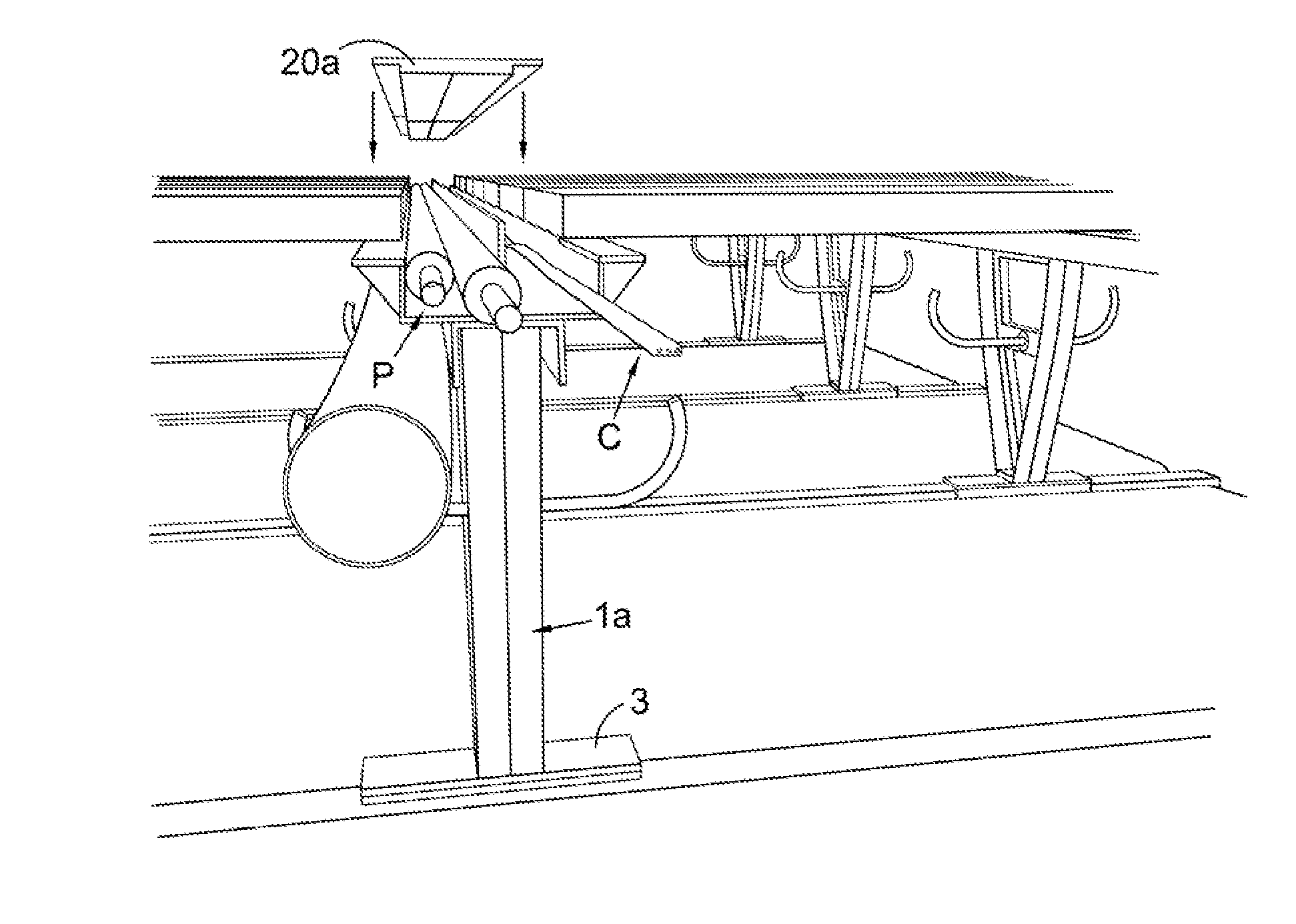
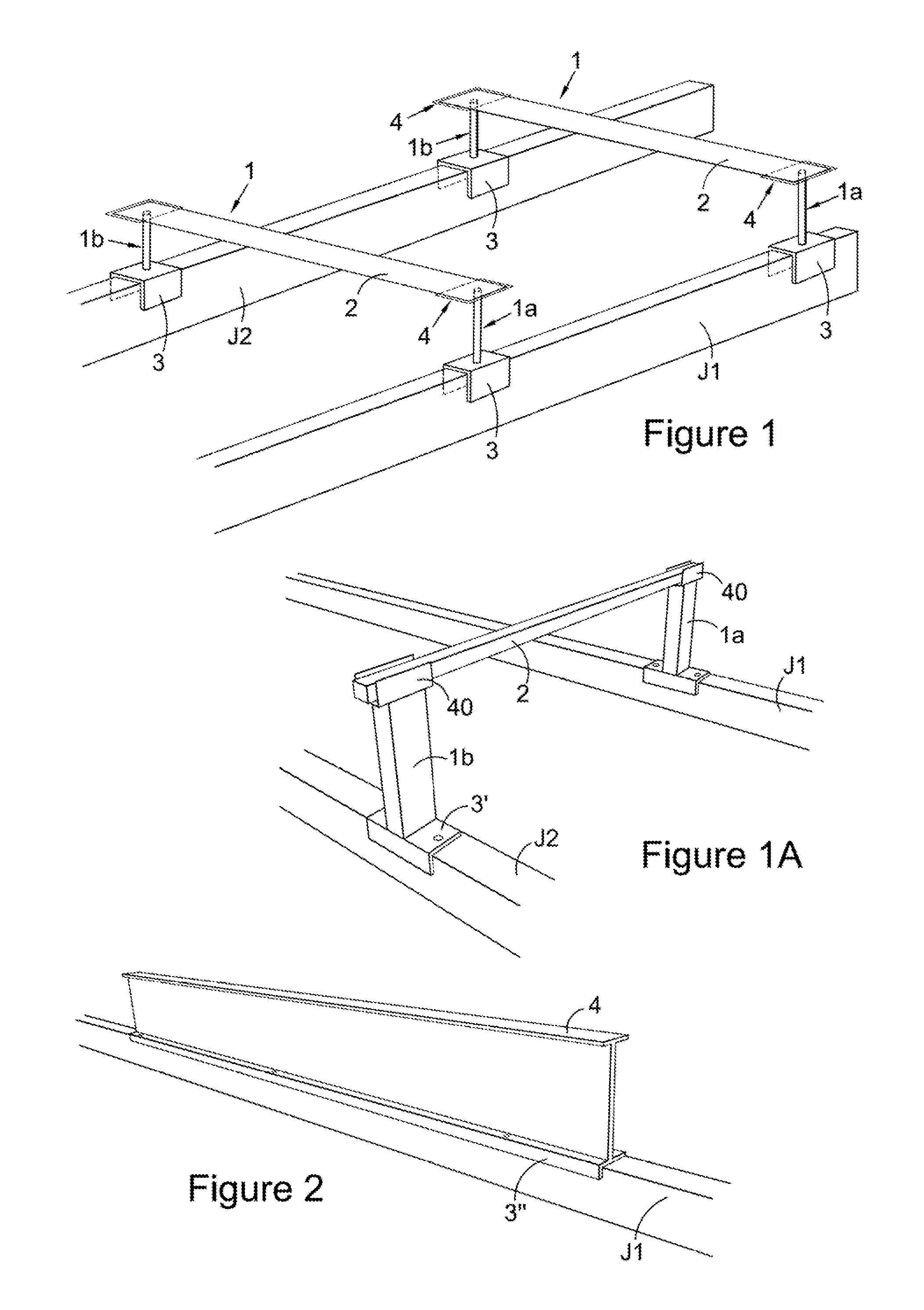
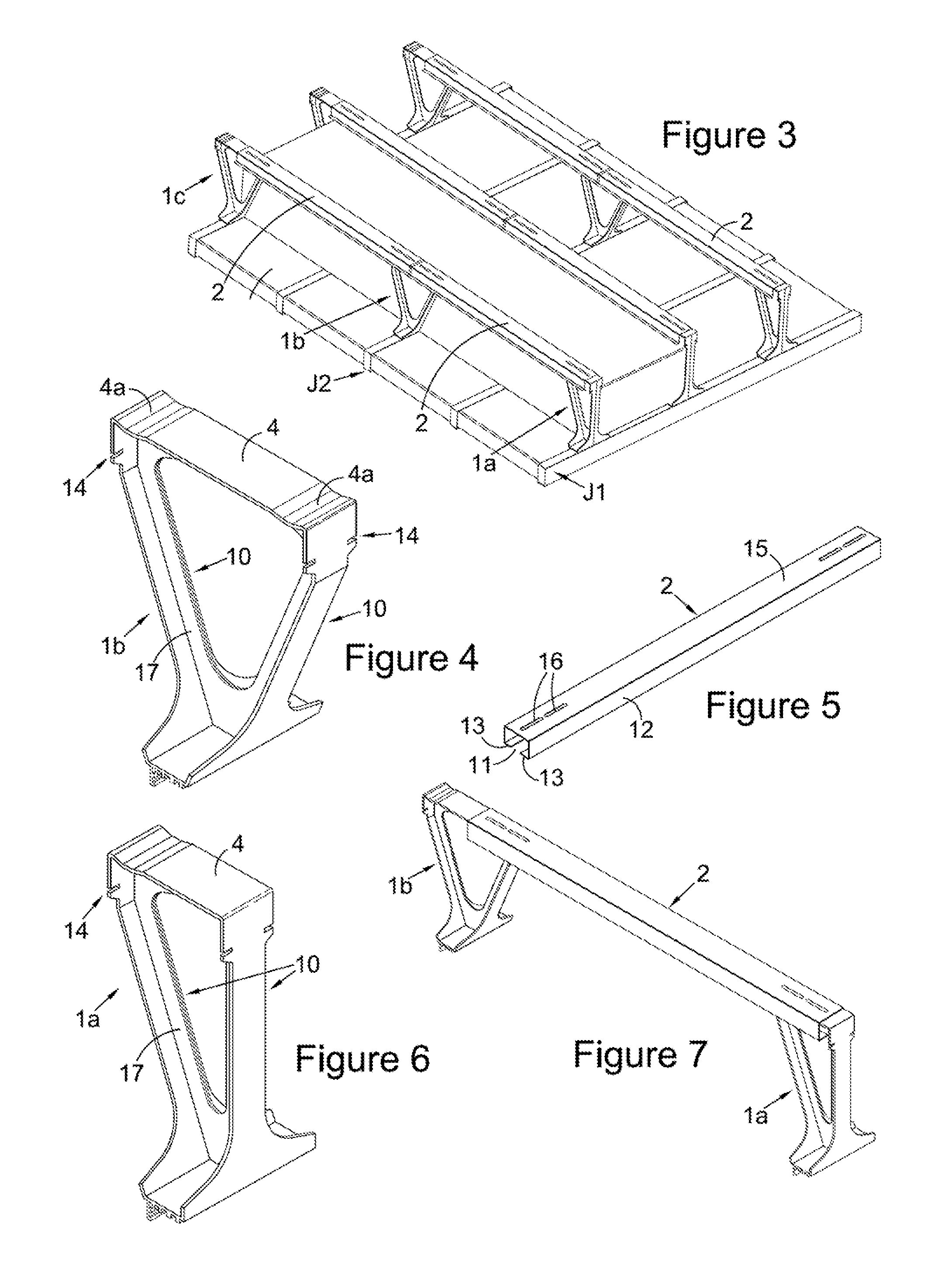
[0085]Referring firstly to FIG. 1, the flooring system comprises a plurality of bridging supports 1 mounted in rows, each row bridging the joists J1, J2 of the loft floor. Each bridging support 1 comprises a pair of initially separate pedestal-type legs 1a, 1b assembled with an overlying spanning element 2 in the form of a metal or timber beam spanning between the tops of the legs 1a, 1b.

[0086]Each leg 1a, 1b of the bridging support 1 comprises a slim but sturdy pillar or pole upright member and that has a foot 3 by which it is mounted to a respective one of a substantially parallel pair of the loft floor joists J1, J2. The foot 3 in FIG. 1 is formed as a saddle, or inverted channel shaped bracket, structure that fits over the top surface and both sidewalls of the respective joist J1, J2 on which it is mounted so that the fit of the foot 3 to that joist J1, J2 limits or substantially prevents movement of the bridging support 1 in both directions orthogonal to the joist J1, J2. In a...


PUM


Abstract

The present invention provides a loft flooring system that, inter alia, comprises: a plurality of bridging supports each adapted to bridge between a substantially parallel pair of joists of a loft floor and having a first upright leg with a foot to mount onto a first of the joists and having, in use, a second upright leg with a foot to mount onto a second of the joists, and a spanning element therebetween defining a flooring surface or onto which flooring boards or flooring panels are laid, wherein each leg is initially separate and the spanning element is an initially separate beam that is mounted to the legs to span between the joists. The system is comparatively straightforward and efficient to install and, where needed, uninstall and also is robust and stable. With special support arms on the legs or hung from the spanning element it can also greatly facilitate discrete management of pipe-work and cabling below the raised floor too.

Description

CROSS REFERENCE TO RELATED APPLICATIONS[0001]This application is a continuation in part of PCT Application Number: PCT / GB2011 / 001022 filed on Jul. 6, 2011 and entitled Loft Flooring System, which claims priority to GB 1101366.1 filed on Jan. 26, 2011 and entitled Loft Flooring System, and GB 1013999.6 filed on Aug. 20, 2010 and entitled Loft Flooring System, all of which are incorporated herein by reference in their entirety.FIELD OF THE INVENTION[0002]The present invention concerns improvements in and relating to loft flooring systems that are adapted to preserve the recommended depth of loft insulation material in the loft when laying the flooring.BACKGROUND TO THE INVENTION[0003]Energy efficiency of buildings is a pressing issue that now affects us all. There is increasingly widespread appreciation of the need for better building insulation to combat thermal energy wastage and its associated costs to the environment as well as the direct cost to the property owner or tenant. Alon...

Claims


Application Information

Patent Timeline
Patent Type & Authority Applications(United States)
IPC IPC(8): E04B5/43E04B5/48
CPCE04B5/12E04B5/43E04F15/02452E04F15/02458E04B5/48E04F15/02044E04F2015/02055E04B1/7654E04F15/18E04B1/76E04F15/024E04B5/023
Inventor CAVE, PIERS ST. JOHN SPENCER GALLIARDGODFREY, PAUL ANDREWLENNAN, DAVID JOHN
Owner NOMINAL SUM
Why Eureka
Try Eureka