Installation element

a technology of installation element and carrier board, which is applied in the direction of threaded fasteners, electrical appliances, fastening means, etc., can solve the problems of reducing affecting the service life of the carrier board, so as to achieve high industrial application, enhance the ease of use, and waste the internal space available

Inactive Publication Date: 2007-07-05
INVENTEC CORP
View PDF10 Cites 9 Cited by
  • Summary
  • Abstract
  • Description
  • Claims
  • Application Information

AI Technical Summary

Benefits of technology

[0016] Yet another objective of the present invention is to provide an installation element for firmly fixing two boards in position and maintaining a gap therebetween.
[0020] In order to fix a main board on a carrier board of limited thickness in a servo device, the bolt of a fixing pillar inevitably projects out of the carrier board according to the prior art. By contrast, the installation element of the present invention is fixed on the carrier board, using a countersink bolt which is screwed into the carrier board from below the carrier board and penetrates the installation opening (a conical-shaped hole) disposed in the carrier and then the installation hole (a threaded hole) disposed in the installation element; the head of the countersink bolt lies flush with the surface of the carrier board after the countersink bolt is driven into the conical-shaped hole. Hence, the present invention has the following advantages.
[0021] First, no bolt protrudes out of the carrier board, thus ease of use is enhanced. Second, the threaded holes disposed in the installation element provide more threads than the carrier board does for a locking purpose, thus the installation element is firmly fixed on the carrier board. Thirdly, the coupling hole for fixing the main board in place and the installation hole for fixing the carrier board in place are not coaxially disposed, thus solving a drawback of the prior art, that is, the fixing pillar gets loosened undesirably as a result of a user's turning a bolt configured to fix the main board in place. And further, rotation of the coupling portion in the positioning opening is restricted because of the profile of the positioning opening and that of the coupling portion; hence, after the coupling portion is positioned in the positioning opening, the installation hole is placed in a position whereby the installation hole is connected and aligned with the installation opening.
[0022] Considering the need to firmly secure a main board in place, a conventional fixing pillar must be of a minimal length, and in consequence the conventional fixing pillar brings about a waste of space when applied in a thin servo device. By contrast, in the present invention, the bolt configured to fix a main board in place penetrates the coupling portion, and the coupling portion looks like a protruding block, which means that the number of threads provided is increased because of the coupling portion; however, the coupling portion is embedded in the carrier board, thus the coupling portion does not widen the gap between the carrier board and the main board at all and waste the internal space available.
[0023] Accordingly, the installation element of the present invention is positioning sensitive, space-saving, and secure and thereby fit to overcome the drawbacks of the prior arts and is highly industrial applicable.

Problems solved by technology

However, there must be a gap between the circuit board and the board for the sake of heat dissipation and prevention of short circuits.
However, a metallic carrier board tends to bring short circuits to the circuits on the main board.
However, when it comes to a servo device of limited height, such as a thin server, the aforesaid solution has its limitation, that is, it ends up with an excessively raised main board with little space for manipulation.
The aforesaid problems, namely simultaneous rotation of a screw and a fixing pillar, insufficient threads, and limited space for manipulation, are not unique to a servo device, but common in whatever devices have two boards installed side by side and a gap maintained therebetween.

Method used


Image

  • Installation element
  • Installation element
  • Installation element

Examples


Embodiment Construction

[0030] The following specific embodiments are provided to illustrate the present invention. Others skilled in the art will readily understand other advantages and functions of the present invention in accordance with the contents disclosed in this specification. The present invention can also be performed or applied by other different embodiments. Various modifications and changes based on different viewpoints and applications can be made in the details of the specification without departing from the spirit of the present invention.

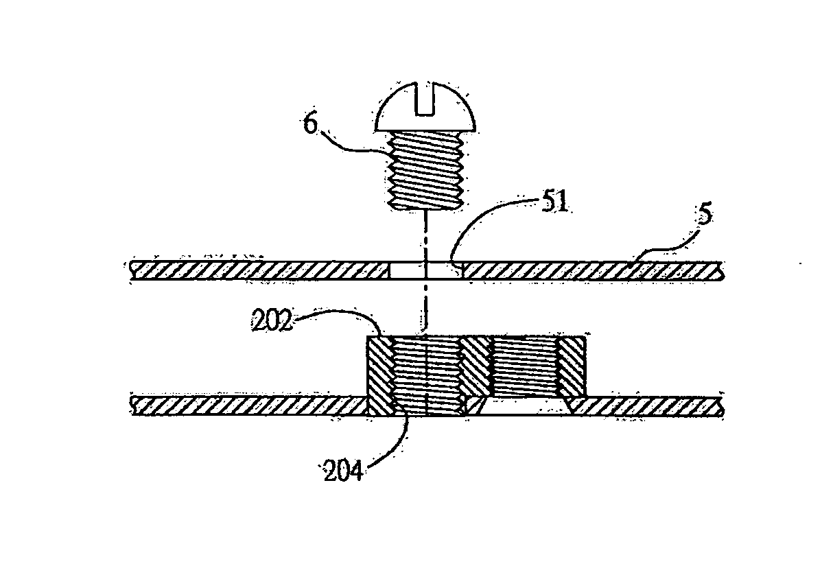
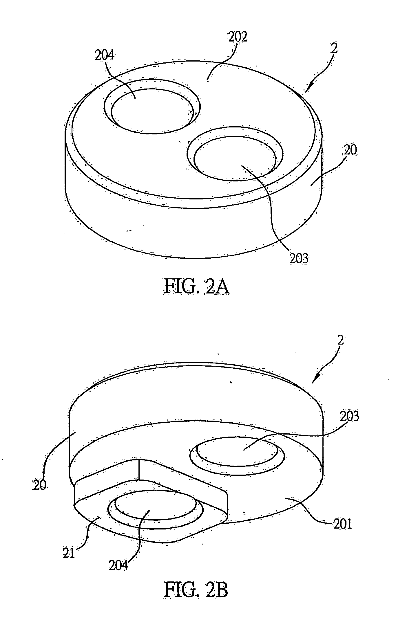
[0031] FIGS. 2 to 5 are diagrams drawn in light of a preferred embodiment of an installation element of the present invention. It should be noted that the installation element described in the following embodiment is applicable to any device having a board, such as a desktop PC, notebook computer, portable electronic product, and servo device. Although an installation element for fixing a main board on a carrier board of a servo device serves as an examp...


PUM


Abstract

An installation element is proposed, which includes a body, a coupling portion, an installation hole, and a coupling hole. The body includes a first surface and an opposing second surface. The coupling portion extends outward from the first surface. The installation hole and the coupling hole, whose axes are parallel, are installed in the body. The installation hole penetrates the body, whereas the coupling hole penetrates both the body and the coupling portion. The coupling portion may be positioned on a board having a positioning opening, such that the coupling portion positionally corresponds to the positioning opening. The board further includes an installation opening connected and aligned with the installation hole, such that not only is the installation element fixed on the board by a coupling element which penetrates both the installation opening and the installation hole, but another board is fixed to the installation element by the coupling hole.

Description

BACKGROUND OF THE INVENTION [0001] 1. Field of the Invention [0002] The present invention relates to an installation element, and more particularly, to an installation element for fixing two boards in position. [0003] 2. Description of Related Art [0004] Since their birth, circuit boards for holding integrated circuits have been widely used in various electronic devices. A circuit board which serves as the main board of an electronic device is typically fixed on a board having an installation function. However, there must be a gap between the circuit board and the board for the sake of heat dissipation and prevention of short circuits. To achieve the aforesaid objective, bumps are disposed on the board, and, alternatively, an installation element is installed on the board so as to fix the circuit board on the board. [0005] As regards a servo device, it is secured on a carrier board locked to a main board. Since the main board usually holds important components installed thereon, suc...

Claims


Application Information

Patent Timeline
Patent Type & Authority Applications(United States)
IPC IPC(8): F16B37/00
CPCF16B5/02H05K7/142F16B37/00
Inventor LIN, LINGER
Owner INVENTEC CORP
Why Eureka
Try Eureka