Compliant pressure roller with uniform nip pressure

a pressure roller and uniform technology, applied in the field of pressure rollers, can solve the problems of inability to achieve the same high tolerance as metallic rollers, inability to grind elastomeric rollers, and inability to recycle carrier webs, etc., to achieve the effect of improving the geometry of die to nip, superior heat transfer capability, and reducing the diameter of the roller

Active Publication Date: 2005-09-08
SK MICROWORKS SOLUTIONS CO LTD
View PDF12 Cites 11 Cited by
  • Summary
  • Abstract
  • Description
  • Claims
  • Application Information

AI Technical Summary

Benefits of technology

[0012] A thin shell on the roller provides finer axial profile adjustment and superior heat transfer capability, which is important for extrusion casting systems. Improved heat transfer may allow for a smaller roller diameter which improves die to nip geomet...

Problems solved by technology

Prior art solutions to the problem of creating a smooth finish have not been completely satisfactory.
Elastomeric rollers, however, cannot be ground to the same high tolerance as metallic rollers.
A problem with this solution is that the carrier web usually must be discarded or recycled adding to the cost of the manufacturing process.
Another problem is that the carrier web often wrinkles.
This solution, however, also has drawbacks.
The thin metal sleeve ...

Method used


Image

  • Compliant pressure roller with uniform nip pressure
  • Compliant pressure roller with uniform nip pressure
  • Compliant pressure roller with uniform nip pressure

Examples


Embodiment Construction

[0019] The present invention will be directed in particular to elements forming part of, or in cooperation more directly with the apparatus in accordance with the present invention. It is to be understood that elements not specifically shown or described may take various forms well known to those skilled in the art.

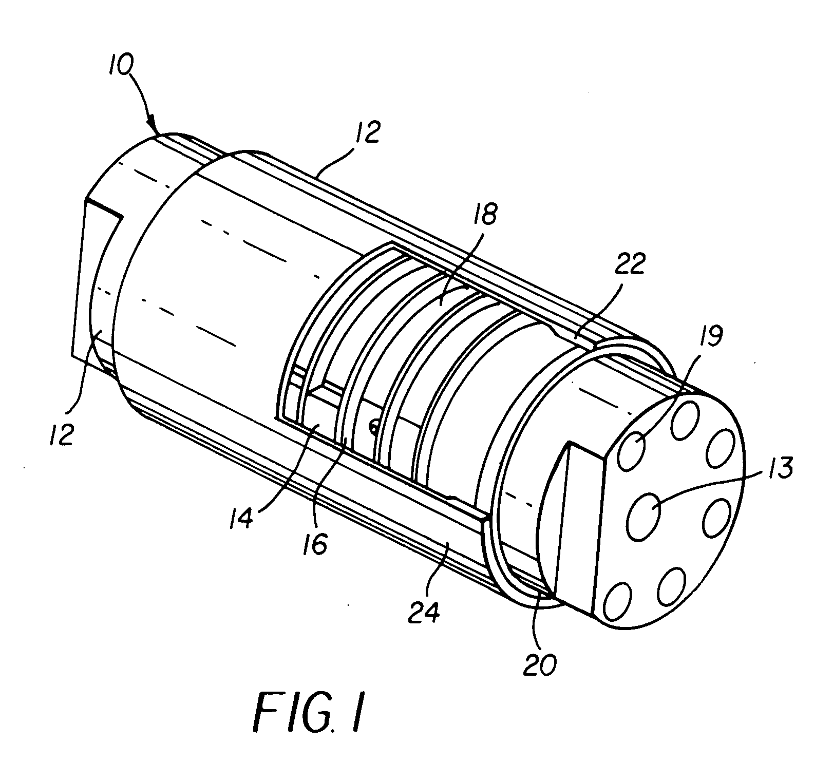
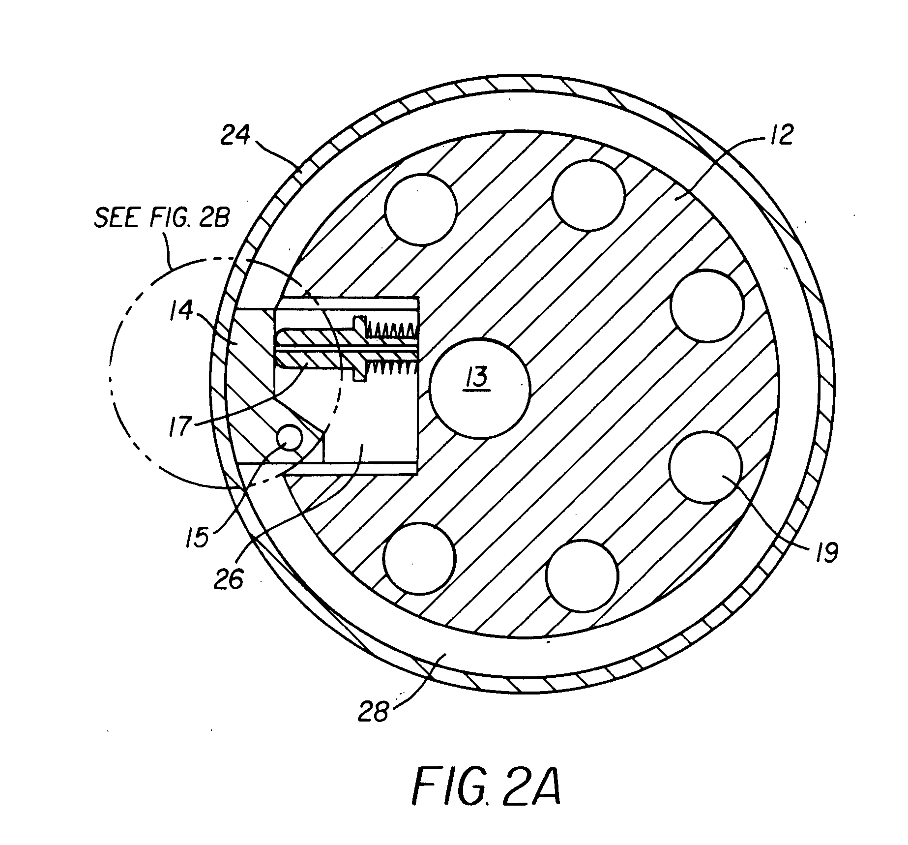
[0020] Referring now to FIG. 1 a compliant pressure roller is referred to in general by numeral 10. Compliant pressure roller 10 is comprised in general of a stationary inner core 12 and a plurality of shoes 14 which are pivotally mounted to the stationary inner core 12. A series of non-magnetic dividers 16 create a plurality of annular chambers 18 and each of the shoes 14 occupies one of the annular chambers 18.

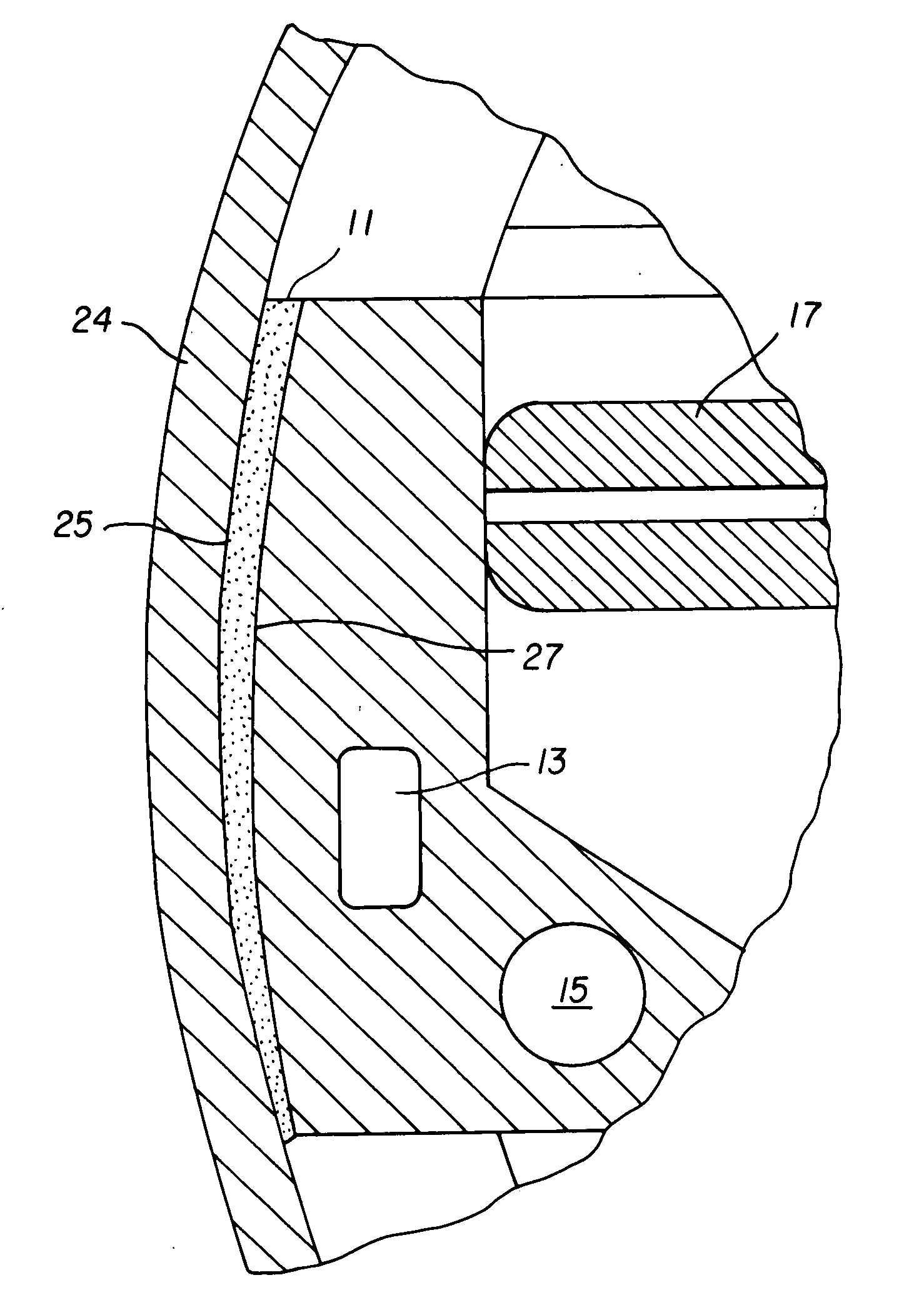
[0021] Referring to FIGS. 1, 2A, and 2B, shoe 14, which is eccentrically mounted, is shown. One surface of shoe 14 is curved. A pivot point 15 and spring loading assembly 17 are attached to shoe 14. A non-magnetic, metallic material is used in the construction o...


PUM

PropertyMeasurementUnit
Thicknessaaaaaaaaaa
Magnetic fieldaaaaaaaaaa
Rheological propertiesaaaaaaaaaa

Abstract

A compliant pressure roller (10) for creating uniform pressure at a nip (42) has a stationary inner core (12). A plurality of shoes (14) is pivotally mounted to the stationary inner core. Non-magnetic dividers (16) create a plurality of annular chambers (18) and one shoe occupies one of the chambers. A magneto-rheological fluid fills each of the chambers and a plurality of magnetic field generators (13) changes a magnetic field in each of the chambers. A thin, rotatable shell (24) surrounds the plurality of chambers, shoes, and stationary inner core.

Description

FIELD OF THE INVENTION [0001] The present invention relates in general to pressure rollers, and in particular, to a compliant pressure roller which adjusts to deformation in a thin outer shell. BACKGROUND OF THE INVENTION [0002] In preparing certain substrates it is important that at least one surface have a smooth finish. Often this smooth finish requires very high tolerances. Prior art solutions to the problem of creating a smooth finish have not been completely satisfactory. One prior art solution has been to use elastomeric rollers. Elastomeric rollers, however, cannot be ground to the same high tolerance as metallic rollers. [0003] Another prior art solution has used carrier webs having a smooth surface finish as a backing material for the substrate as it passes through the nip. A problem with this solution is that the carrier web usually must be discarded or recycled adding to the cost of the manufacturing process. Another problem is that the carrier web often wrinkles. [0004]...

Claims


Application Information

Patent Timeline
IPC IPC(8): B21B27/05B21B37/30D21G1/02F16C13/00F16C17/03F16C33/10
CPCB21B27/05B21B37/30F16C33/10F16C13/028F16C17/03D21G1/022F16C13/00F16C33/04
Inventor BOMBA, RICHARD D.BLISH, NELSON A.
Owner SK MICROWORKS SOLUTIONS CO LTD
Why Eureka
Try Eureka