Road/rail vehicle with load-shifting device

a technology of load-shifting device and road/rail vehicle, which is applied in the direction of locomotives, retractable wheels, transportation and packaging, etc., can solve the problems of high cost, high cost, and inconvenient use of traditional locomotives, and achieve the effect of sufficient weigh

a technology of load-shifting device and road/rail vehicle, which is applied in the direction of locomotives, retractable wheels, transportation and packaging, etc., can solve the problems of high cost, high cost, and inconvenient use of traditional locomotives, and achieve the effect of sufficient weigh

US20050204949A1Inactive Publication Date: 2005-09-22RAIL SERVICE & LOGISTICS

Image

  • Road/rail vehicle with load-shifting device
  • Road/rail vehicle with load-shifting device
  • Road/rail vehicle with load-shifting device

Examples


Embodiment Construction

[0017] Reference will now be made to the exemplary embodiments illustrated in the drawings, and specific language will be used herein to describe the same. It will nevertheless be understood that no limitation of the scope of the invention is thereby intended. Alterations and further modifications of the inventive features illustrated herein, and additional applications of the principles of the invention as illustrated herein, which would occur to one skilled in the relevant art and having possession of this disclosure, are to be considered within the scope of the invention.

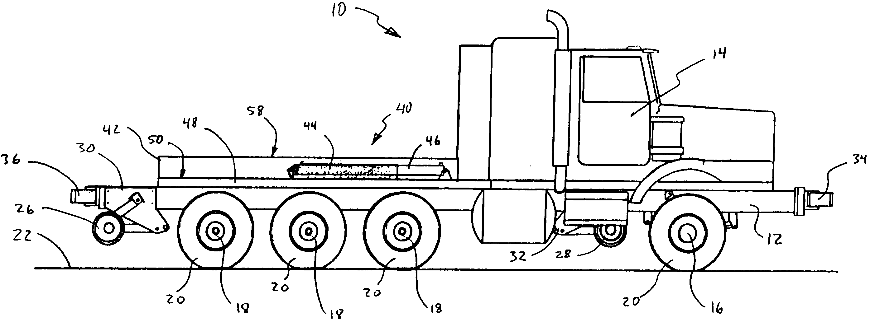
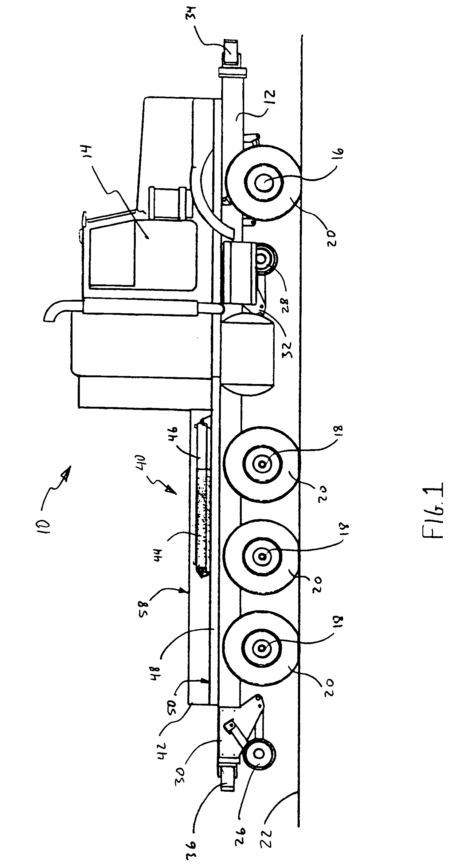
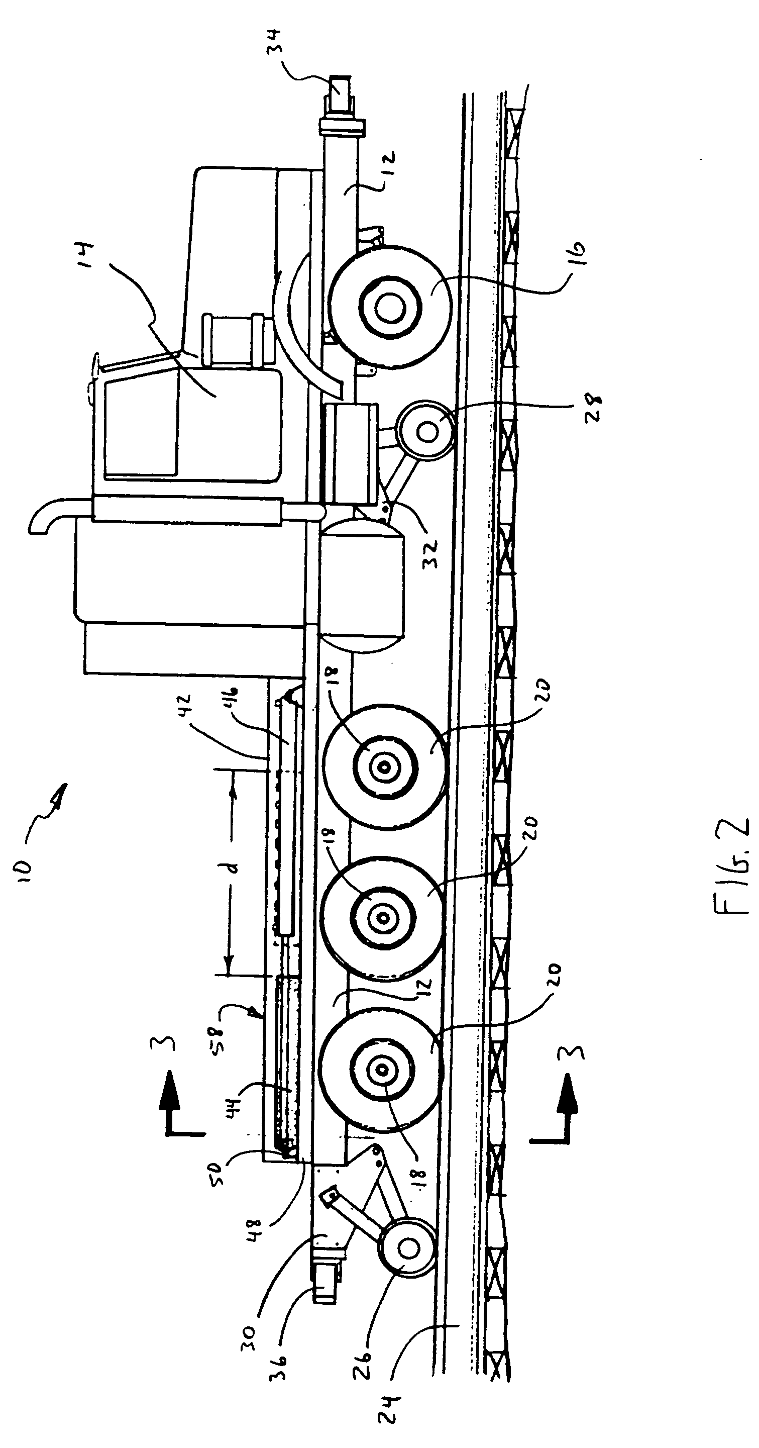
[0018] Shown in FIGS. 1-3 are side and rear views, respectively, of a railcar-moving vehicle 10 comprising a modified semi tractor that is convertible for use both on highways and on rails. The modified semi tractor is a conventional semi tractor in most respects, having an elongate frame 12, a cab 14 housing the engine and controls, front wheels 16 and a series of rear drive wheels 18. The front wheels and rear...


PUM


Abstract

A railcar-moving vehicle comprises a modified semi-tractor, having a highway mode for operation on roadways, and a rail mode for operation on rails. The vehicle includes an elongate frame with selectively extendable high rail wheels for guiding the vehicle on rails, and rubber-tired drive wheels for operation on roadways. The rubber-tired drive wheels are configured to support the vehicle on a roadway in highway mode, and to contact the rails in rail mode. A moveable weight is disposed on a rear portion of the frame. A load-shifting mechanism moves the moveable weight between a rearward position for rail mode and a forward position for highway mode.

Description

BACKGROUND OF THE INVENTION [0001] 1. Field of the Invention [0002] This invention relates to railcar-moving vehicles that are adaptable both for moving railcars along railroad track and for driving on roadways. [0003] 2. Related Art [0004] In the railroad industry, maintenance of way is a critical activity and a major expense. Frequently, when maintenance is needed at a particular location along the right-of-way and heavy equipment or materials are required, a work train and crew are sent to that location to perform the needed repairs. For example, a work train may carry a load of railroad ties and short sections of rail for repairing track, and may include some pieces of heavy equipment for unloading and installing these items. Often, a work train consists of a locomotive pulling a single work car, and the maintenance work can be performed by one or two workers. [0005] However, this approach can be very cost inefficient. Because maintenance of way crews and locomotive crews are di...

Claims


Application Information

Patent Timeline
22 Sep 2005
Publication
US20050204949A1
IPC
B60F1/04; B61C11/00; B61D15/00; B61F13/00
CPC
B60F1/04; B60F2301/04; Y02T30/30; B61D15/00; B60F1/005; Y02T30/00
Inventors
JACOB, CHARLES