Endoscope angle portion

a technology of endoscope and angle portion, which is applied in the field of angle portion structure, can solve the problems of poor operation, deformation or damage of the flexible tube that makes up the insertion channel of the operative instrument,

Inactive Publication Date: 2005-11-24
FUJI PHOTO OPTICAL CO LTD
View PDF10 Cites 17 Cited by
  • Summary
  • Abstract
  • Description
  • Claims
  • Application Information

AI Technical Summary

Benefits of technology

[0017] Generally, in the case of an arrangement enabling bending in four directions, the maximum curvature of bending is enabled for bending in the upward direction. As the angle ring unit in this case, a pair of front and rear angle rings, which are pivotally joined so as to enable bending in the left and right directions, make up a singl

Problems solved by technology

Insertion of a forceps or other operative instrument of poor insertion condition in a passage that is sharply bent in this manner accompanies high resistance against insertion and not only is the operability poor but the inner surface

Method used


Image

  • Endoscope angle portion
  • Endoscope angle portion
  • Endoscope angle portion

Examples


Embodiment Construction

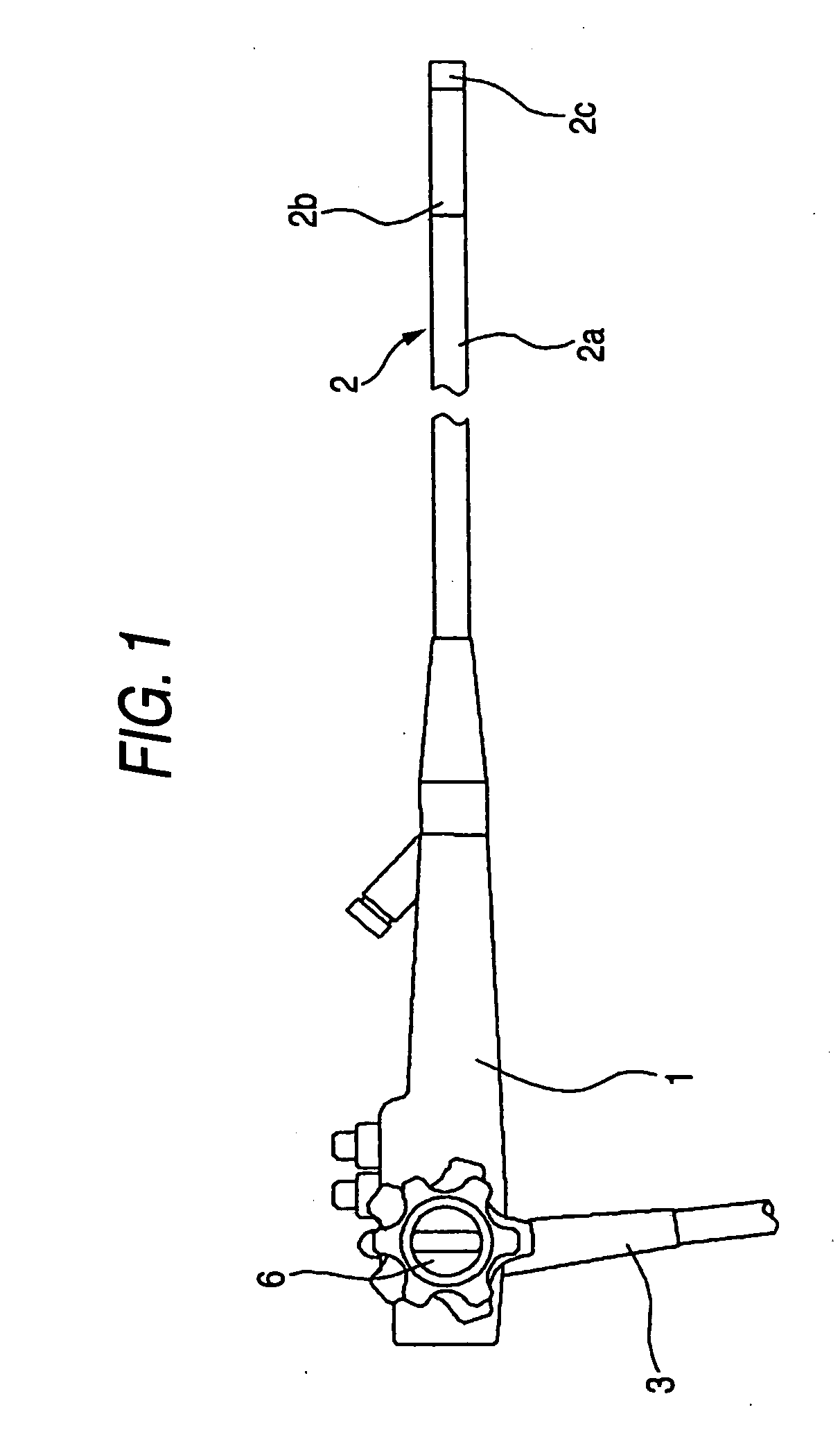
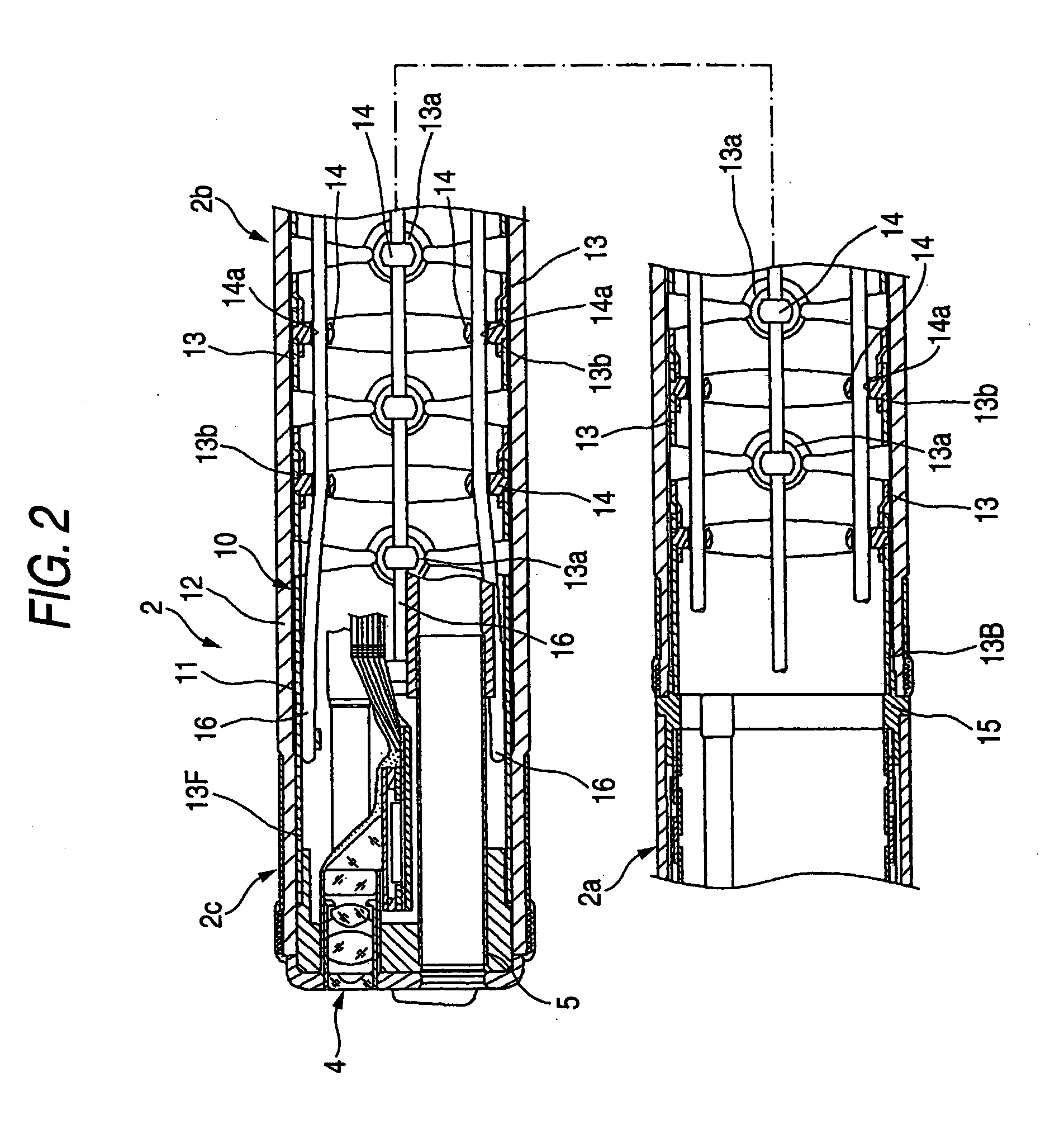
[0025] An embodiment of the present invention shall now be described with reference to the drawings. FIG. 1 shows the overall arrangement of an endoscope and FIG. 2 shows a cross section of a front end section of an insertion portion.

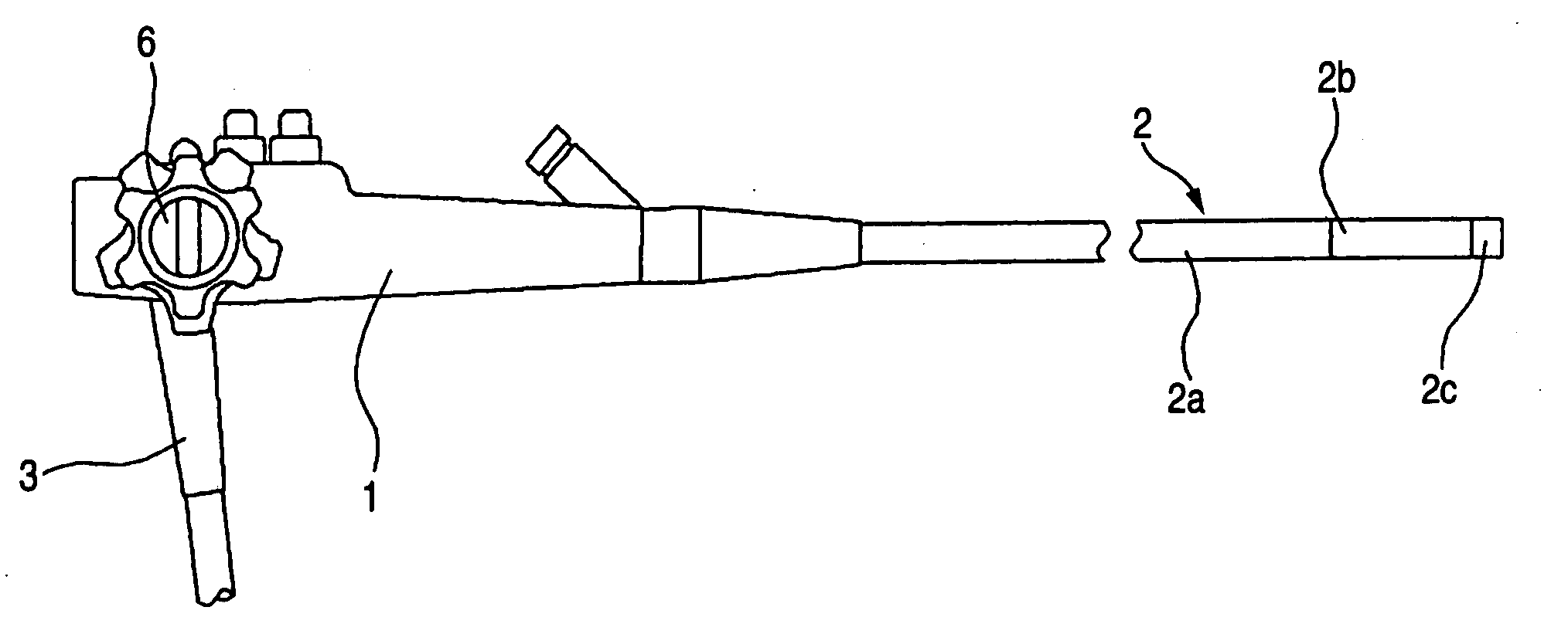
[0026] Firstly, in FIG. 1, 1 is a body control portion, 2 is an insertion portion, and 3 is a universal cable. The body control portion 1 is held by one hand and operated by an operating surgeon or other endoscope operator, and the insertion portion 2 is inserted inside a body cavity. The universal cable 3 is equipped with a light source connector, the other end of which is detachably connected to a light source device. A connector for connection to a processor, which is provided integral to or separate from the light source device, is also equipped in the case of an electronic endoscope. The arrangement of the end section of the universal cable 3 is well known and illustration and description thereof shall be omitted.

[0027] The insertion portion 2 ha...


PUM


Abstract

An endoscope angle portion comprises an angle portion structure. The angle portion structure includes angle ring units each of which comprises pivoting joint portions extending from its both ends and has a shape that is notched obliquely in directions away from the pivoting joint portions, and wherein adjacent ones of the angle ring units is pivotally joined to form the angle portion structure, wherein a first angle ring unit of the angle ring units has a larger length dimension than that of a second angle ring unit of the angle ring units, and the first angle ring unit has a smaller notch width of a notched portion than that of the second angle ring unit, the first angle ring unit being nearer a base end of the endoscope angle portion than the second angle ring unit.

Description

BACKGROUND OF THE INVENTION [0001] 1. Field of the Invention [0002] This invention relates to the structure of an angle portion that makes up an insertion portion of an endoscope used for medical use, etc. [0003] 2. Description of the Related Art [0004] Generally, with an endoscope for medical use, etc., an insertion portion, for insertion into a body cavity, etc., is connected to a body control portion, and a universal cable, which is detachably connected at least to a light source device, is lead out to the body control portion. The insertion portion comprises, in the order from the side connected to the body control portion, a flexible portion, an angle portion, and a distal end hard portion, and the angle portion, which is connected to the front end of the flexible portion, which can be bent in an arbitrary direction in accordance with an insertion path of the insertion portion, is a portion that can be operated to become bent by an angle control section disposed at the body con...

Claims


Application Information

Patent Timeline
IPC IPC(8): A61B1/00G02B23/24A61B1/005A61B1/05
CPCA61B1/05A61B1/0055
Inventor MACHIYA, MAMORUAKIBA, HARUO
Owner FUJI PHOTO OPTICAL CO LTD
Why Eureka
Try Eureka