Pneumatic design method for ultrahigh-load, ultralow-rotating-speed and large-bypass-ratio fan rotor

A technology of fan rotor and large bypass ratio, which is applied in the direction of machine/engine, jet propulsion, etc., can solve the problems affecting the stator and rear stage design, achieve high efficiency and low speed design, reduce overall weight, and reduce fan noise Effect

Inactive Publication Date: 2015-12-09
NANJING UNIV OF AERONAUTICS & ASTRONAUTICS
View PDF5 Cites 10 Cited by
  • Summary
  • Abstract
  • Description
  • Claims
  • Application Information

AI Technical Summary

Problems solved by technology

This method can effectively reduce the difficulty of rotor design, but if the rotor mer...

Method used


Image

  • Pneumatic design method for ultrahigh-load, ultralow-rotating-speed and large-bypass-ratio fan rotor
  • Pneumatic design method for ultrahigh-load, ultralow-rotating-speed and large-bypass-ratio fan rotor
  • Pneumatic design method for ultrahigh-load, ultralow-rotating-speed and large-bypass-ratio fan rotor

Examples


Embodiment Construction

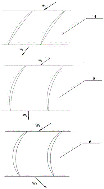
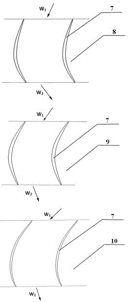
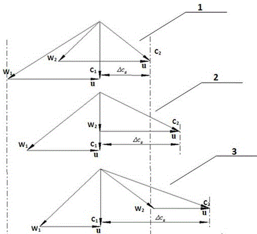
[0026] The following combination Figure 1 to Figure 5 The aerodynamic design method of the fan rotor with ultra-high load, ultra-low speed and large bypass ratio of the present invention is illustrated. ①According to the given flow rate and pressure ratio, the key design parameters are determined by S2 through-flow analysis. The key design parameters include: speed, blade twist, blade inlet and outlet root and tip radii, number of blades, rotor inlet and outlet fluid parameter distribution ; and the load factor , the value of which should be selected to achieve the relative speed of the rotor outlet W 2 greater than the inlet relative velocity W 1 . ②According to the rotor inlet and outlet parameter distribution (including the velocity triangle) determined by the S2 flow design, carry out several S1 flow surface two-dimensional airfoil 7 designs (only typical blade root, blade center, and blade tip blade shapes are given here. ), the airfoil design can be carried out by ...


PUM


Abstract

The invention relates to a pneumatic design method for an ultrahigh-load, ultralow-rotating-speed and large-bypass-ratio fan rotor, and belongs to the technical field of impeller machinery. The pneumatic design method includes the steps that firstly, key design parameters are determined through S2 through-flow analysis according to flow and the overall pressure ratio, and the load coefficient is selected between 0.7 and 1.0; secondly, a plurality of S1 stream surface two-dimensional blade forms (7) are designed according to the inlet and outlet parameter distribution, determined according to S2 through-flow analysis, of the rotor; thirdly, the two-dimensional blade forms designed in the second step are stacked in the radial direction to form three-dimensional blades (11), and the fan rotor (12) is formed according to the number of selected blades; and fourthly, the performance curve of a fan is obtained by conducting three-dimensional flow field simulation of the fan rotor (12) through computer simulation or conducting performance tests through experiments, whether design reaches the standard and meets the requirement or not is tested, and improved design is conducted. By means of the pneumatic design method for the ultrahigh-load, ultralow-rotating-speed and large-bypass-ratio fan rotor, on the premise of ensuring the pneumatic performance of the fan, noise and the weight of the fan are effectively reduced.

Description

technical field [0001] The invention relates to a fan aerodynamic design method of a turbofan engine with a large bypass ratio, and belongs to the technical field of impeller machinery. Background technique [0002] Large civil airliners all use turbofan engines with high bypass ratio as the power plant of the aircraft; engine noise is an important evaluation index, and the large-size fan (professional name: high bypass ratio fan) installed at the engine inlet accounts for the entire contribution to the noise. It is about one-third of the noise of the machine; reducing the fan speed is an effective way to reduce its noise; and the reduction of the speed can reduce the structural strength requirements of the fan blades, and the blades can be designed to be lighter and thinner, thereby reducing the weight of the fan. For gear-driven fans, the speed of the fan can be reduced by increasing the gear reduction ratio, keeping the speed of the booster stage of the compressor connect...

Claims


Application Information

Patent Timeline
IPC IPC(8): F02K3/04
Inventor 周正贵张金环崔翠
Owner NANJING UNIV OF AERONAUTICS & ASTRONAUTICS
Why Eureka
Try Eureka