Method and system for communicating video data in a packet-switched network, related network and computer program product therefor

a packet-switched network and video data technology, applied in the field of communication systems, can solve the problems of video frames being dropped, limited bandwidth availability, and inflexible solutions

Active Publication Date: 2005-12-01
STMICROELECTRONICS SRL
View PDF7 Cites 96 Cited by
  • Summary
  • Abstract
  • Description
  • Claims
  • Application Information

AI Technical Summary

Benefits of technology

[0145] The method of the present invention thus estimates link quality based only on layer-2 (header compressor) and lay

Problems solved by technology

This solution is not very flexible.
The increased overhead is due to packet headers, such a circumstance being particularly undesirable in cellular systems characterized by limited (and costly) bandwidth availability.
However, current mobile videoconferencing systems do not exploit information available at different layers of the protocol stack to optimize the quality of the video-call: in this way, if the wireless channel conditions change, video frames may be dropped and errors may corrupt images for quite a long time.
In particular, from the end user point of view, the impression of the connection quality is very often related to the delay experienced on the connection.
The mobile environment is characterized by harsh transmission conditions in terms of attenuation, fading, and shadowing, which may result in time-varying channel conditions.
However, these advanced tools can provide a negligible radio block error rate only for a relatively large value of tolerated maximum delay, whereas some amount of residual errors has to be tolerated for low-delay applications.
Another critical aspect concerning wireless video communication is that in general, the available bandwidth (and thus the bit-rate) over the radio link is limited and the costs for the user are expected to be proportional to the number of transmitted bits over the radio link.
Contrarily, Unacknowledged Mode does not use any retransmission protocol, which implies that data delivery is not guaranteed.
In Unacknowledged Mode large Realtime Transport Protocol packets are more

Method used


Image

  • Method and system for communicating video data in a packet-switched network, related network and computer program product therefor
  • Method and system for communicating video data in a packet-switched network, related network and computer program product therefor
  • Method and system for communicating video data in a packet-switched network, related network and computer program product therefor

Examples


Embodiment Construction

[0154] The goal of the present arrangement is the optimization of an IP-based video-call application between two terminals, in which at least one of them is a mobile one.

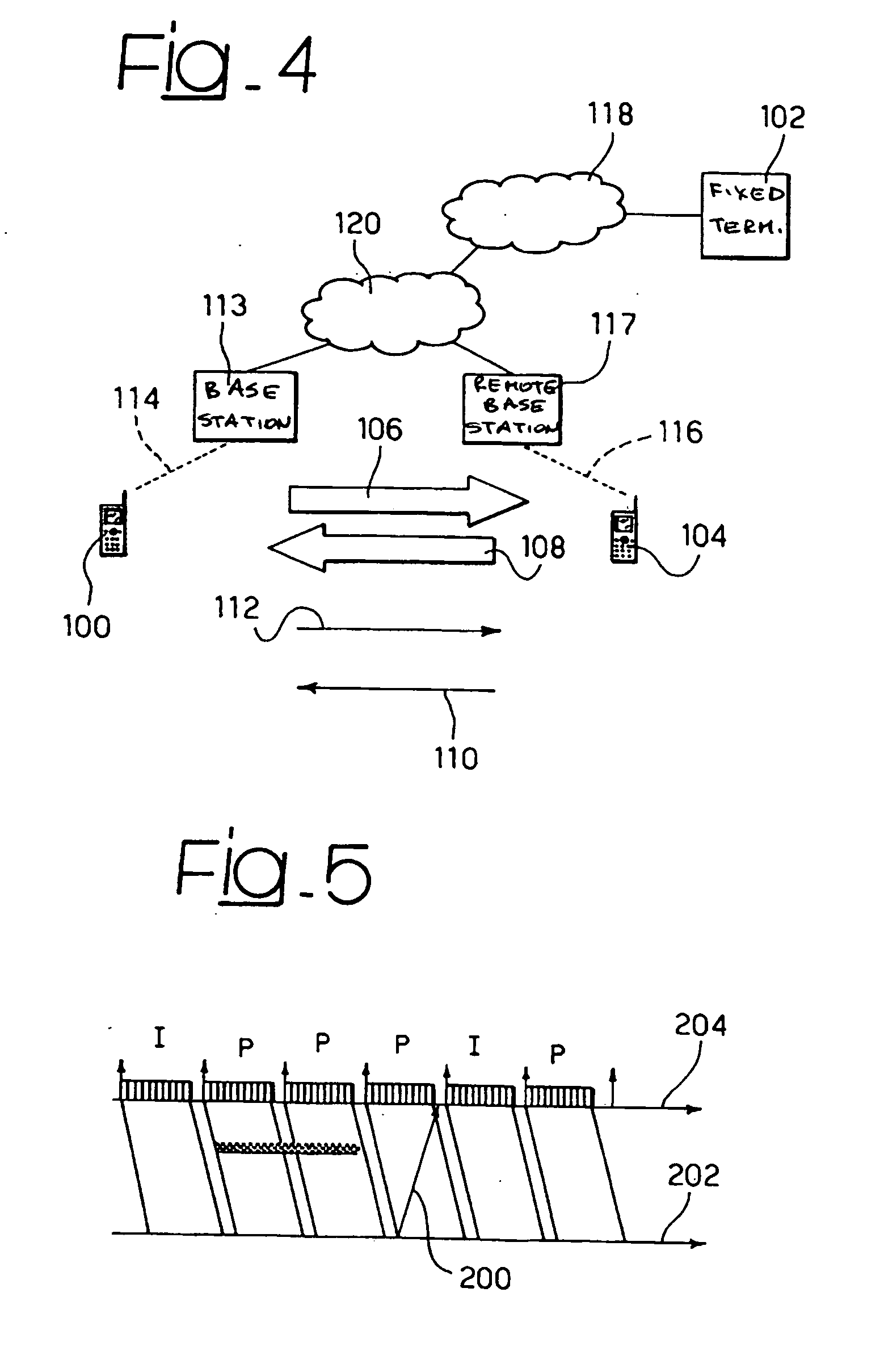
[0155] A system architecture is depicted in FIG. 4 for further reference, where a mobile terminal 100, corresponding to the User Equipment cited in the standard, is shown. Such a mobile terminal 100 communicates through a local link 114 with a base station 113, that in its turn is communication with a controller network 120, according to a typical mobile telecommunication architecture. A further remote mobile terminal 104 is shown, communicating with a remote base station 117 through a remote link 116, and thereby connected to the controller network 120. Also a fixed terminal 102 is shown, that can communicate with the controller network 120 through a Internet network 118.

[0156] The video-call application can either run between the mobile terminal 100 and the fixed terminal 102 or between the mobile terminals 100 ...


PUM


Abstract

A method for communicating video data on a wireless channel in a packet-switched network includes the steps of operating at a wireless terminal a compression in packets on the video data during a video coding operation, detecting wireless channel conditions and adapting control parameters of the video coding operation to the detected wireless channel conditions. The compression operation is a robust header compression operation and the step of adapting control parameters of said video coding operation is performed in dependence of information about the wireless channel conditions detected on a feedback channel made available in a decompression step associated with the compression operation.

Description

RELATED APPLICATION [0001] The present invention claims priority of European Patent Application No. 04012878.7, which is incorporated herein by this reference in its entirety. 1. FIELD OF THE INVENTION [0002] The present invention relates to communication systems, and was developed by paying specific attention to mobile and wireless video communication systems. [0003] In particular, this invention proposes a new technique for adapting the behavior of a video coder to the channel conditions, especially in the case of a wireless channel. 2. DESCRIPTION OF THE RELATED ART [0004] Nowadays, mobile bi-directional video communication applications use circuit-switched channels and the H.324M protocol stack defined by the International Telecommunication Union (ITU). Static encoding schemes like H.263 with fixed output stream bitrate and coding parameters are used. This solution is not very flexible. [0005] Packet-switched networks, on the contrary, offer a higher degree of flexibility especi...

Claims


Application Information

Patent Timeline
IPC IPC(8): H04J3/16H04J3/18H04J3/22H04L1/00H04L1/16H04L12/66H04N7/24H04N19/89H04Q7/00
CPCH04L1/0014H04L1/0026H04L1/0083H04L1/16H04N21/2343H04N21/2402H04N19/174H04N21/44245H04N21/6437H04N21/8451H04N19/89H04N19/503H04N21/44209
Inventor MELPIGNANO, DIEGOOLIVIERI, STEFANO
Owner STMICROELECTRONICS SRL
Why Eureka
Try Eureka