Hydraulic control apparatus

a technology of hydraulic control apparatus and control cylinder, which is applied in mechanical apparatus, shock absorbers, transportation and packaging, etc., can solve the problems of not teaching or suggesting changes to the control characteristic of hydraulic control cylinder, and the conventional hydraulic control cylinder is not versatil

Inactive Publication Date: 2005-12-08
TOYOTA JIDOSHA KK
View PDF4 Cites 3 Cited by
  • Summary
  • Abstract
  • Description
  • Claims
  • Application Information

AI Technical Summary

Benefits of technology

[0007] It is therefore an object of the present invention to provide a versatile hydraulic control apparatus.

Problems solved by technology

However, in the above-indicated hydraulic control cylinder, the piston assembly is moved with a substantially constant ease (or difficulty) over an entirety of a permitted movement range in which the piston assembly is permitted to move.
Thus, the above-indicated U.S. Patent does not teach or suggest changing the control characteristic of the hydraulic control cylinder, depending upon a specific object of a suspension system including the suspension cylinders or devices.
That is, the conventional hydraulic control cylinder is not versatile.

Method used


Image

  • Hydraulic control apparatus
  • Hydraulic control apparatus
  • Hydraulic control apparatus

Examples


Embodiment Construction

[0044] Hereinafter, there will be described preferred embodiments of the present invention by reference to the drawings.

[0045] 1. Suspension System of a Vehicle

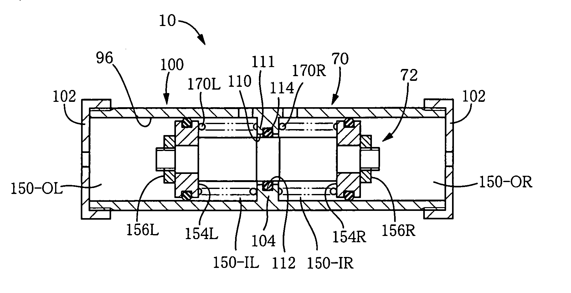
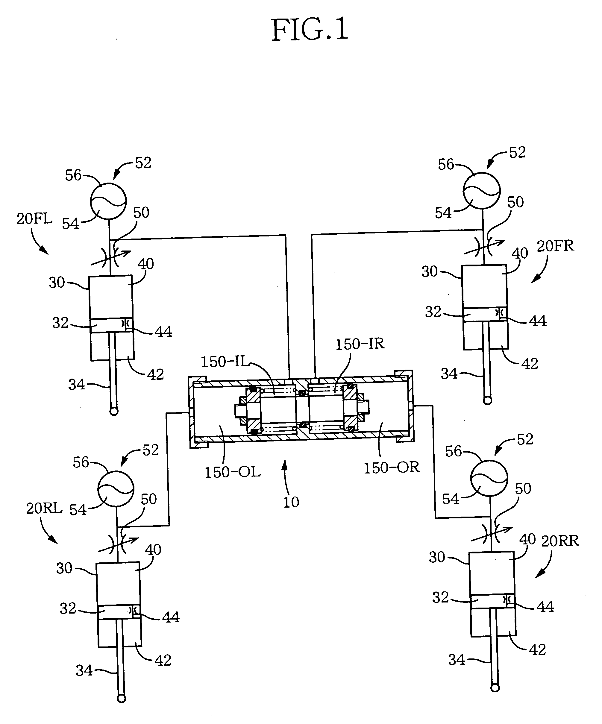
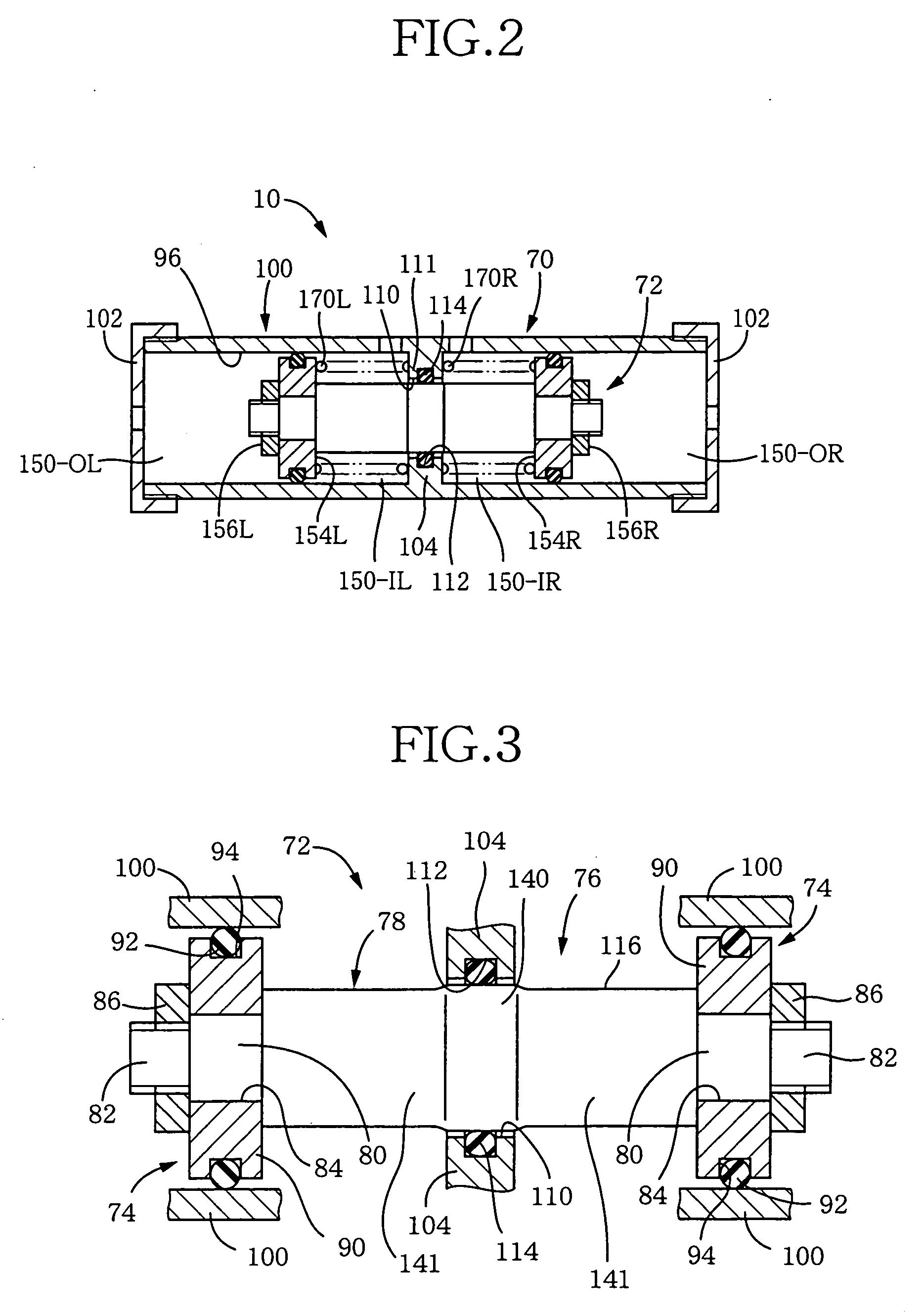
[0046]FIG. 1 diagrammatically shows a hydraulic control cylinder 10 as an embodiment of a hydraulic control apparatus of the present invention, and a portion of a suspension system of a vehicle which portion is related to the hydraulic control cylinder 10. The suspension system includes, in addition to the hydraulic control cylinder 10, four hydraulic suspension cylinders 20 (20FL, 20FR, 20RL, 20RR) that are respectively provided for four wheels of the vehicle. The four hydraulic suspension cylinders correspond to hydraulic suspension devices. Each of the four suspension cylinders 20 is provided between a body of the vehicle and a corresponding one of the four wheels, and functions as a shock absorber that produces a damping force when the one wheel is moved upward and downward, i.e., is moved toward, and away from, the bod...


PUM


Abstract

A hydraulic control apparatus including a housing including first sliding-related portions; a piston assembly including second sliding-related portions which cooperate with the first sliding-related portions to provide pairs of first and second sliding-related portions; and elastically deformable sealing members each of which is supported by one of the first and second sliding-related portions of a corresponding one of the pairs, such that the each sealing member is slideable on the other of the first and second sliding-related portions. The pairs of first and second sliding-related portions and the sealing members cooperate with each other to separate an inner space of the housing into hydraulic chambers. When the piston assembly is moved in the housing in a movement direction, the each sealing member supported by the one of the first and second sliding-related portions is slid on the other of the first and second sliding-related portions, and a volume of each of the hydraulic chambers is changed. At least one pair of first and second sliding-related portions of the pairs of first and second sliding-related portions exhibits, when the piston assembly is positioned, in the movement direction, at different positions relative to the housing, different resistances to the movement of the piston assembly relative to the housing.

Description

[0001] The present application is based on Japanese Patent Application No. 2004-166704 filed on Jun. 4, 2004, the contents of which are incorporated herein by reference. BACKGROUND OF THE INVENTION [0002] 1. Field of the Invention [0003] The present invention relates to a hydraulic control apparatus (e.g., a so-called “hydraulic control cylinder”) for use in a suspension system of a vehicle, and in particular to such a hydraulic control apparatus that is connected to each of a plurality of hydraulic suspension devices (e.g., so-called “hydraulic suspension cylinders”) respectively provided for a plurality of wheels of a vehicle and controls an operation of the each suspension device. [0004] 2. Discussion of Related Art [0005] An example of the above-indicated hydraulic control apparatus is disclosed by U.S. Pat. No. 3,024,037. The disclosed hydraulic control apparatus or cylinder includes a housing having a partition wall, and a piston assembly including two pistons that cooperates ...

Claims


Application Information

Patent Timeline
Patent Type & Authority Applications(United States)
IPC IPC(8): B60G17/033B60G17/056B60G21/06B60G21/10F16F9/08F16F9/18
CPCB60G17/033B60G17/056B60G21/06B60G21/10B60G2204/8306B60G2204/81B60G2204/82B60G2204/8304B60G2202/154
Inventor HASHIMOTO, NAOYUKI
Owner TOYOTA JIDOSHA KK
Why Eureka
Try Eureka