Method of forming a perforated composite panel

a composite panel and perforated technology, applied in the direction of manufacturing tools, controlling lamination, transportation and packaging, etc., can solve the problems of inability to heat the chemical composition of the applied layer, damage to the applied layer, and inability to drill through the hole by conventional methods

Inactive Publication Date: 2017-04-04
ROLLS ROYCE PLC
View PDF6 Cites 0 Cited by
  • Summary
  • Abstract
  • Description
  • Claims
  • Application Information

AI Technical Summary

Benefits of technology

[0012]In one embodiment of the invention, the liner panel may comprise of one or more applied layers attached to a substrate where the applied layer materials have a different resistance to machining than the substrate. The applied layers may be used to provide corrosion protection or thermal insulation to the substrate.
[0036]In one embodiment, a multi-head drilling machine may be employed to cut several holes simultaneously so making the method of the invention simpler, quicker and therefore more efficient for a user.

Problems solved by technology

The drilling of a through-hole by conventional methods may be impractical as it may cause damage to the applied layers.
Furthermore, the chemical composition of the applied layers may not be suited to heating, for example by a laser.

Method used


Image

  • Method of forming a perforated composite panel
  • Method of forming a perforated composite panel
  • Method of forming a perforated composite panel

Examples


Embodiment Construction

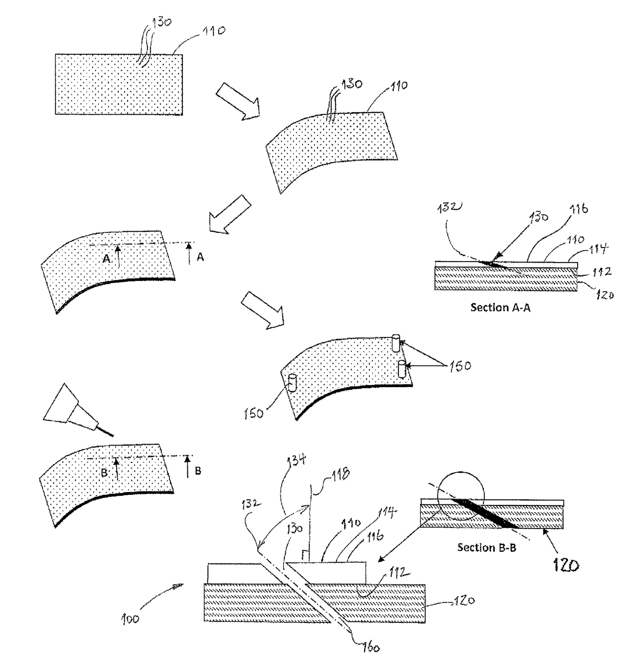
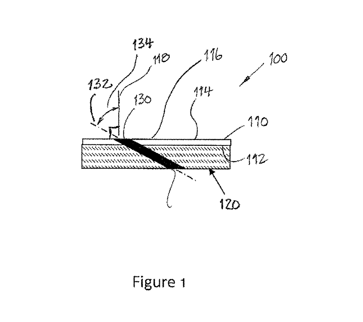
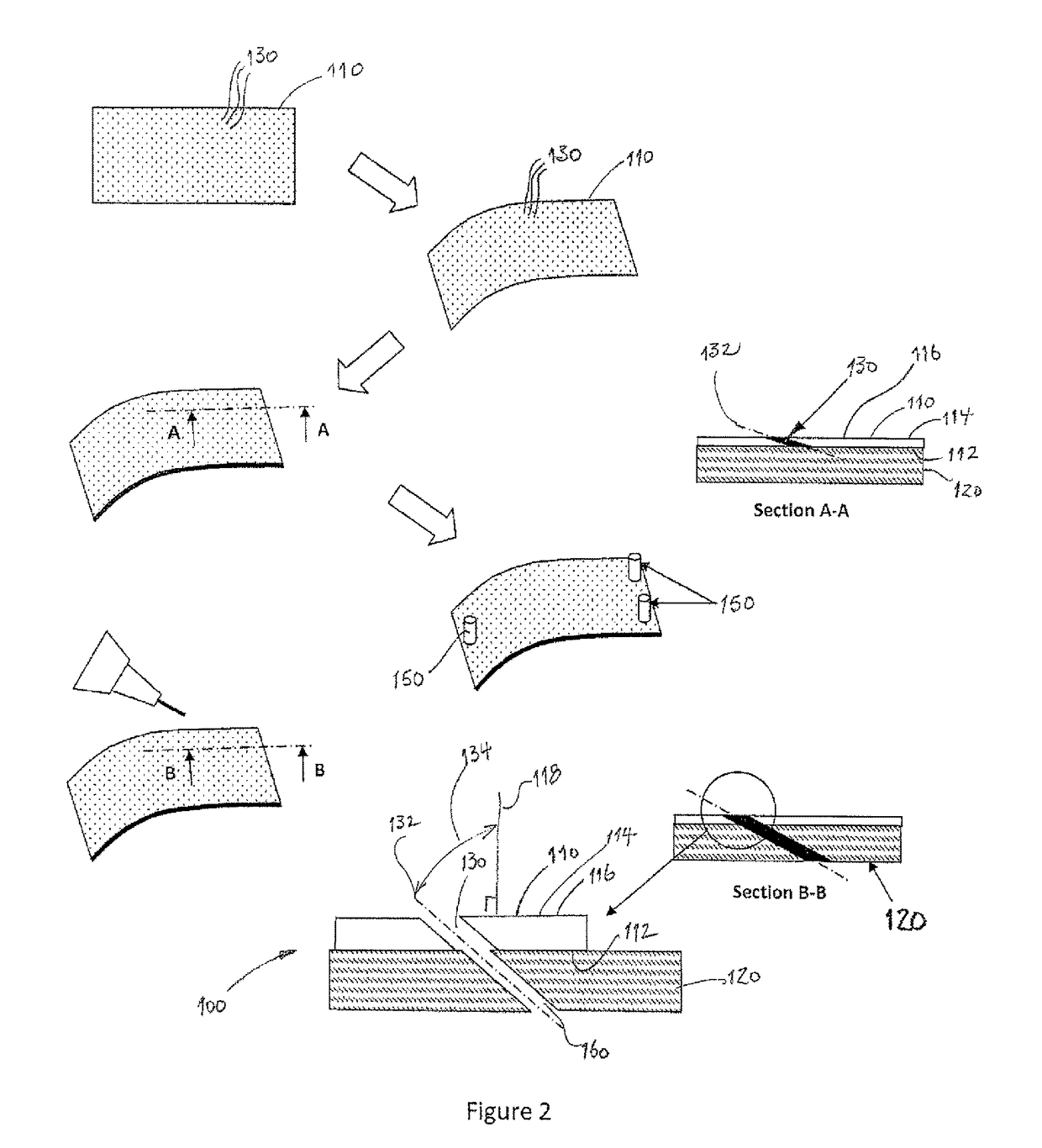
[0043]Referring to FIG. 1, a perforated composite panel formed by an embodiment of the invention is designated generally by the reference numeral 100.

[0044]The perforated composite panel 100 comprises a substrate 110 and an applied layer 120. The substrate 110 has a first surface 112 and an opposite second surface 114. The applied layer 120 extends over and covers the first surface 112 of the substrate 110.

[0045]The perforated composite panel 100 forms a liner panel 100 for the exhaust system (not shown) of a gas turbine engine (also not shown). The gas turbine engine is installed in an aircraft (also not shown) but may equally be installed in another form of transport (also not shown) or even in a stationary installation (also not shown) such as, for example, an electrical power generating installation (also not shown).

[0046]In the embodiment shown the substrate 110 is formed as a titanium alloy sheet. Alternatively the substrate 110 may be formed from another metal or metal alloy ...


PUM

PropertyMeasurementUnit
angleaaaaaaaaaa
angleaaaaaaaaaa
diametersaaaaaaaaaa

Abstract

A perforated composite panel comprises a substrate and an applied layer, the substrate having a first surface and an opposite second surface. A method of forming the perforated composite panel comprises the steps of:i. cutting a plurality of first holes in the substrate;ii. positioning the applied layer against the substrate such that a surface of the applied layer overlays the first surface of the substrate to thereby form the composite panel;iii. locating the composite panel in a fixture, the fixture having one or more datum features;iv. determining the location and axis direction for each of the first holes in the substrate, relative to the or each datum feature; andv. cutting a plurality of second holes in the applied layer, each of the plurality of second holes being coincident and coaxial with a corresponding one of the plurality of first holes.

Description

FIELD OF THE INVENTION[0001]The present invention relates to a method of forming a perforated panel and particularly to a method of forming a perforated composite panel.BACKGROUND TO THE INVENTION[0002]In a typical aircraft propulsion system it is known to use liner panels to isolate the hot exhaust gas stream from the exhaust casing and to thereby form a guided path for the cooling air flow. To prevent the hot gas stream from overheating the liner panel it is known to incorporate holes in the liner panel, through which cooling air is flowed. This creates a barrier of cool air between the hot exhaust gas stream and the exhaust casing.[0003]This cooling air is typically directed at an angle to the liner panel in order to increase the cooling efficiency, to minimise entry losses, to improve the mixing between the exhaust gas stream and the cooling air flow. This angle may be up to 70 degrees to the exhaust liner surface normal.[0004]These cooling holes are typically formed by laser or...

Claims


Application Information

Patent Timeline
Patent Type & Authority Patents(United States)
IPC IPC(8): B32B37/12B32B41/00B32B38/00B32B38/04B23B35/00B32B3/26
CPCB32B38/0004B23B35/00B32B3/266B32B38/04B32B41/00B23B2215/04B23B2228/36B23B2270/58B32B37/12B32B2038/047B32B2262/106B32B2311/18Y10T156/1056Y10T156/1057B23B41/16B23B2247/10
Inventor HAYTON, PAUL ROBERT
Owner ROLLS ROYCE PLC
Why Eureka
Try Eureka